All things G1176 - the new "repost" thread.

GroupDIY Audio Forum

Help Support GroupDIY Audio Forum:

This site may earn a commission from merchant affiliate links, including eBay, Amazon, and others.
[quote author="3nity"]To Gswan.
I took out the transformer and tested outside the circuit.
It works just fine.

I tried to do the Calibration but my meter wont move more than half a 1db.[/quote]

Maybe you can describe what you did.
It's probably better to test the various circuit sections to see that they are working correctly before doing calibration.

Firstly with no signal applied, measure the DC bias conditions at each transistor leg and verify that they are correct.

Then use a 1kHz signal into the input and measure the signal at various points through the audio circuitry. This allows you to check the gains of the various stages and verify that they are operating correctly. There's some detail here.

http://www.axtsystems.com/index.php?view=article&catid=34%3A1176ln&id=57%3A1176lnproblems&option=com_content&Itemid=62

Once you've done this you can then calibrate it with reasonable confidence that it's going to work.

Geoff
 
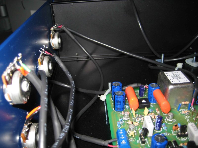
3nity, here's a picture of mine with OEP input and the two 12k's in place just
behind it, leads are covered as the original Lundahl bumped up against it :


93610915.jpg


Worked fine for me, more on that at Mnats 1176 page I think.

Marty.
 
[quote author="MartyMart"]3nity, here's a picture of mine with OEP input and the two 12k's in place just behind it, [/i][/quote]

shouldn't that be 10K for OEP?

Iain
 
See thats why we need this forum!
I tested again...my bad some wiring was just bad!!!


ARgh my meter dont reach 0 db. it stops at 2db!
but i bought it like this!!!

again i'm waiting for some nice VU meters to fit all this into a 1u rack!
:thumb:
 
[quote author="lofi"][quote author="MartyMart"]3nity, here's a picture of mine with OEP input and the two 12k's in place just behind it, [/i][/quote]

shouldn't that be 10K for OEP?

Iain[/quote]

You may be right Iain, but what's 2k between friends ??
I think I'd used up my 10k's at that point ( along with some others they are
first to go ! )
I'm not too anal about exact values, lots of times I just get "close" , like using
4k7 for a 4k3 etc , or joining a couple of resistors to get close.
MM.
 
Hey gswan , thanks for the info,

I'm meauring ratios , from a starting point of 8dB gain reduction already in place , assuming that is well out of the knee..

hmm ..I suspected that the only way might be with adjusting the resistor network , seeing as no-one seems to be bothering about this much..yeah I can see it will be a lot more fiddly than fine tuning the gssl was...so cheers for that!

I'll definitely give it some closer attention though..something to come back to , when I've finished the current 1176 build.
I presume that the ratios would also differ , from one FET to another ,but i dunno.. and if that IS so ..then tuning resistor values could easily become a "wild goose chase"..

cheers

nEon
 
The ratios should not differ between FETs, since Qbias calibration will place each FET to a known state of conduction. The slope of the linear section of the curves for these FETs is very close, even though the saturation and pinch-off points vary considerably.

The ratios are set by the GR amp section, which has quite a bit of variability. The ratio resistor tolerance will have effects, as will the values of the various resistors in the GR amp section (which is really a rectifier circuit). The low-leakage diodes also will affect the ratios since their characteristics will be different.
 
Thanks again, gswan...Yeah I hadn't thought about the Qbias factor ,but I see your point!

It's funny , I always go thru a load of resistors to pick out the closest values whenever I stuff the boards , but this particular 1176 is a very early build ,for me, and I probably have used a few more carbon resistors than i would nowadays..that may be part of the issue.
As i said , when I get the chance , I'll look into it further , and those pointers you gave me will help.

Cheers !

nEon
 
I thought I should seek professional guidance when it came to this section of the wiring of my Mnats Rev. J 1176.. Im willing to sacrifice a few caps or whatever if I wiring something wrong, but when it comes to the mains I want to make sure I get it right the first time..

So i received my Antek Inc toroidial transformer today in the mail and it has alot of wires on it and I need to know what goes it where..

There are 2 red, 2 black, 2 green, 2 blue. The red and black are labelled as 115v, the red and blue as 25v. So I get obviously that the red and black go from the main power, then the green and blue are the reduced voltage. I think the most confusing part for me is why is there 2 sets of each wire? are they all supposed to do something different or can you just stick the blues together and the greens together and so forth?

I remember there was some sort of transformer wiring explanation at one point but I cant find it because the search is broken for me..

Any help would be appreciated to help me figure out where the wires go :)

Thanks
Andre
 
the two red go together and the blacks together....secondaries are green together as center tap and your blues hook up to the psu AC.
 
[quote author="3nity"]the two red go together and the blacks together....secondaries are green together as center tap and your blues hook up to the psu AC.[/quote]

Thanks! Just so i'm 100% clear, center tap is ground? Im still getting used to these lingo's

Thanks again

Andre
 
Check the manufacturer's datasheet on this.

The reason there is two primary windings is that they can be wired in parallel for 115V or series for 230V mains.

The two secondary windings are each 25VAC windings. If the green/blue mark the winding start/finish ends then you would wire it so that you had [blue]...[green+blue]...[green] where the green+blue connection would be the centre tap. This places the windings in series. However you need to check the data sheet to make sure that the colour coding is indeed marking the start/finish of the windings.
 
[quote author="adoucette"][quote author="3nity"]the two red go together and the blacks together....secondaries are green together as center tap and your blues hook up to the psu AC.[/quote]

Thanks! Just so i'm 100% clear, center tap is ground?[/quote]

NM! Had a moment of "duh" there. Center tap is the middle pin between the two 24v pins on the psu right?
 
The switch and fuse should be used to disconnect the incoming mains supply, not post-transformer. Otherwise your transformer is powered up all the time so if the transformer overheats or develops a fault you would have no simple means of disconnection.
 

Latest posts

Back
Top