[BUILD] fripholm's TG1 Zener Limiter boards - support thread

GroupDIY Audio Forum

Help Support GroupDIY Audio Forum:

This site may earn a commission from merchant affiliate links, including eBay, Amazon, and others.
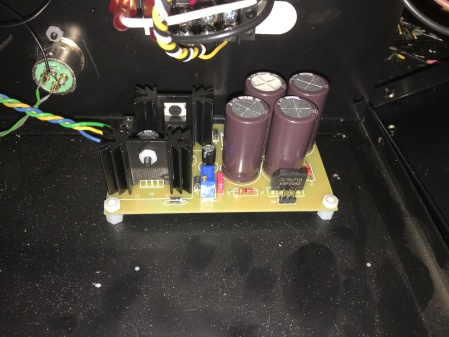
Here's about the best picture I can get. It's fripholm's PSU board.

2018-10-29-22-52-20.jpg
 
Great.... Doesn't look like your filter caps are backwards........ Can't imagine they'd be bad.....
.... I'm sure fripholm or others will have some direction to get this ball rolling.... maybe I'm looking at your issue wrong...circuit is unique to other ones.....

These things look pretty sweet..... you'll get it figured out.... don't give up....
...... 


If you disconnect the boards from PSU do you still see AC at the PSU output (when unloaded)? If yes, that's where your problem is.
Otherwise it may be an oscillation. But it must be very huge. Do you have a scope? Can you see what that AC looks like?
 
So far this looks like a grounding issue. Unfortunately, I'm drowning in work at the moment. Hopefully I will have some time tomorrow and can take a look at this and reply.
 
Ilya said:
If you disconnect the boards from PSU do you still see AC at the PSU output (when unloaded)? If yes, that's where your problem is.
Otherwise it may be an oscillation. But it must be very huge. Do you have a scope? Can you see what that AC looks like?

I was seeing the AC, even with the power supply unloaded. So I went and changed my PSU star ground connection from the PSU input to the PSU output, and I'm beyond thrilled to report that absolutely all AC voltage is now gone from my power supply. I plugged in a board to do a quick check, and again, no more random AC. I wish I had the rest of the day to test out my circuit and see if it'll actually pass audio now. I feel pretty silly now shelving this project for a year, only to find out it was grounding issue, the solution of which was even offered to me way back when I was having the problems in the first place  :p

Oh well! Better late than never. I'm just happy to finally be making progress on this beast again.
 
Back again!

Got my relays wired up today, since I still hadn't taken care of that. Also wired up my meter lights, because I needed anything to lift my spirits with this project.

Wired up a board, hooked up a test signal to the input XLR, etc. No signal :(
Double checked my relays and the wiring to/ from. Everything checks out. I can read AC coming out of the input transformer, but only the one that isn't hooked up to the relay yet. The one that is attached to the relay reads no voltage at the relay connection.

I remember having this problem before, so I read back through the thread and saw to test by injecting the signal directly into the middle pad of Bypass 2. Tried that and was happy for a moment because I saw some signal coming through my interface, but when I turned the volume up I realized that it wasn't really signal coming through at all, just some very quiet noise.
Took the signal coming from the output XLR into my multimeter ad I was getting some really bizarre results. Touching the test lead to the middle pad gave me a spike of AC, but even after I took the lead off of the pad, there was still an AC signal coming from the output cable. It seemed to be fluctuating pretty rapidly, it read around 3-4VAC, but it was never audible through my interface.

So I guess I'm back to square one as far as this project goes. Seems like all of my problems are coming from the output stage. I'll have to double check my voltages now that I cleaned up the AC from my power supply.
 
James, I think you have too many variables to deal with when doing the third step before the first and wire up the relays before even getting the basic functionality of the unit right. Do this when everything else is working!
 
fripholm said:
James, I think you have too many variables to deal with when doing the third step before the first and wire up the relays before even getting the basic functionality of the unit right. Do this when everything else is working!
Fripholm is right,you‘ll most likely end with a messed up unit and totally disappointed.
That is not a propper way to sort out possible issues.The key is patience and logical thinking.
Please always read carefully and follow his recommendations.Take a deep breath and start again.


Best regards,


Udo.
 
kante1603 said:
Fripholm is right,you‘ll most likely end with a messed up unit and totally disappointed.
That is not a propper way to sort out possible issues.The key is patience and logical thinking.
Please always read carefully and follow his recommendations.Take a deep breath and start again.


Best regards,


Udo.

+1..... I was reading the guide and got scared...lol .... Definitely a lot of room for error if not paying strict attention to all the details......

JCN---- wiring looks crazy nice so,the detail is there..... I know you'll get it..... Just take as long as you need.......
 
Fair points guys! I'm not sure what it is about this project that has me so anxious to finish it. Probably just the amount of time it's been on the bench.

Anyway, took some time yesterday to take the relays out. I left the meter lights wired up, just disconnected its feed from the power supply.

Still getting the same issues from my last post. No signal reading at the pole of my switch, and when directly injecting the signal I'm still getting those strange results.

Seems like there must be an issue in the output section still, but also somewhere around the input as well.

When I get some more free time, I'm going to triple check my off-board wiring to confirm that all the pads have connectivity to the front panel components that they're supposed to be connected to.

Thanks to everyone for all the help so far. I feel pretty determined that I'll have this thing up and running soon.
 
Rome wasn't built in a day........or something like that.....

There are only a handful of components in the output section so, that should be easy enough to get past. The flipping orientation or misplacing  of things (transistors) can definitely cause other issues but maybe you got lucky....

Testing transistors, diodes, reading resistances, checking for bridges or cold joints.......all doable with a simple multimeter.... Transistors and diodes are most likely culprits after wiring or user mistakes from my experience..... sometimes caps..... shouldn't take hardly any time to find anything that looks questionable....

LCR meters are nice to have to check capacitors as well...

Then, after everything checks out or is addressed you can at least be ready to test the output section like was mentioned earlier after your other issues are sorted.....????

Good luck!

 
Not yet  :( Progress has been very slow, unfortunately. I've been recording/mixing my band's new album and that's been taking up most of my free time lately.

I've checked the off-board connections for most of one board so far, and it looks like I may have a mixup somewhere in the SC section, but I'm not 100% sure yet. Still need to diagnose what's going on in the output section as well. Supposed to snow here today, so maybe that'll free up some DIY time for me. I'll definitely keep you guys posted!
 
PRICE DROP!

Until December 31st, 2018 the price for one of my TG1 limiter boards is just 30 Euros plus shipping.
 
Hi all!

Slowly working to assemble the parts to start this build. 

Sorry if this was covered earlier in this thread, I must have missed it if so... wondering what the minimum enclosure depth I should consider when using fripholm's PCB's and PSU PCB in a stereo configuration?  The PCB's are rather small, so I'm wondering if I can get away with an enclosure smaller than 14" in depth without running into access and / or power supply or wire routing noise issues? 

Thanks in advance!
Greg
 
ron_swanson said:
Hi all!

Slowly working to assemble the parts to start this build. 

Sorry if this was covered earlier in this thread, I must have missed it if so... wondering what the minimum enclosure depth I should consider when using fripholm's PCB's and PSU PCB in a stereo configuration?  The PCB's are rather small, so I'm wondering if I can get away with an enclosure smaller than 14" in depth without running into access and / or power supply or wire routing noise issues? 

Thanks in advance!
Greg

You could easily use a 14" depth rack case with room to spare.
 

Latest posts

Back
Top