CLX-VU Build Thread (DBX 160VU ) UPDATE: REV 3

GroupDIY Audio Forum

Help Support GroupDIY Audio Forum:

This site may earn a commission from merchant affiliate links, including eBay, Amazon, and others.
Shot,

I'd defo try to stick within the 1% range, do you have any similarly high value resistors to see if your DMM is misbehaving?  Last time that happened to me I needed to change the batteries...  :-[ :-[ :-[


I finished mine about the same time as Majestic12 but didn't want to share the limelight!  ;)

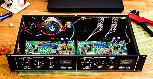
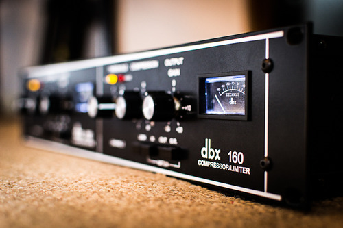
Pics of the finished unit:

tumblr_inline_mfwfh1A0Ea1r2bfgn.jpg


tumblr_inline_mfwflcAhZ11r2bfgn.jpg


tumblr_inline_mfwflvwV7v1r2bfgn.jpg


Cheers,

Ian.
 
Damn! It never crossed my mind that it could be multimeter's batteries! I'll swap them tomorrow!

All resistors I'm using are metal film 1%.
Today I went to some other shops and I still cannot find values like 23K2, 5K49, 6K04, 133K and 22Meg.
I could combine few resistors to get the desired value.
Should I do it?
Or I can order from Farnell (only they have representative here in croatia), but the smallest quantity would be 50 pcs of every value. That would be buying 250 resistors to use only 6 of them!

What would happen if I put 5K6 instead of 5K49?
The 5K6 actually measures 5K56. That is close. Less than 2% off.
If I go 22K1+1K1 to get the 23K2?
If I use 6K19 (measuring real value of 6K13) instead of 6K04?
And so on... (100K+33K=133K, 10M+10M+2M=22M)
 
shot said:
Damn! It never crossed my mind that it could be multimeter's batteries! I'll swap them tomorrow!

All resistors I'm using are metal film 1%.
Today I went to some other shops and I still cannot find values like 23K2, 5K49, 6K04, 133K and 22Meg.
I could combine few resistors to get the desired value.
Should I do it?
Or I can order from Farnell (only they have representative here in croatia), but the smallest quantity would be 50 pcs of every value. That would be buying 250 resistors to use only 6 of them!

What would happen if I put 5K6 instead of 5K49?
The 5K6 actually measures 5K56. That is close. Less than 2% off.
If I go 22K1+1K1 to get the 23K2?
If I use 6K19 (measuring real value of 6K13) instead of 6K04?
And so on... (100K+33K=133K, 10M+10M+2M=22M)

DO it! I wouldn't worry about it TOO much. Should be fine. Remeber a lot of these parts back then were 5% when they built them. Just take notice of the resistors in the RMS unit, try to get those as close as possible. The closer the better, but I doubt a few percentages off will do anything to adverse.
 
Anyone know what is differences between silver and black cans? I have silver on my build but original 160 have black can, right?
 
late said:
Anyone know what is differences between silver and black cans? I have silver on my build but original 160 have black can, right?

My understanding is the Silver cans were a little bit more nosier...by how much im not too sure. If anyone has any hands on experience I would like to know too.
 
Hey abe, I have an 'odd' question for you  :eek:

I have two 20K and one 22K linear pots. Can I use the 22K instead of getting a new 20K and if so where would be more appropriate (threshold, ratio or make up gain)?  :)

thanks
w.
 
abechap024 said:
late said:
Anyone know what is differences between silver and black cans? I have silver on my build but original 160 have black can, right?

My understanding is the Silver cans were a little bit more nosier...by how much im not too sure. If anyone has any hands on experience I would like to know too.
  FWIW, here's a quote from the THAT corp that mentions the Silver Can and noise,
"...dbx chose to develop its own Class A VCA, the dbx 2001, housed in a silver can. Class A operation resulted in a substantially higher noise  floor, resulting from higher current through the gain cell and the correspondingly higher shot noise. However, some users claimed to prefer the sound of this device because of its lower THD."

Lots of other great info on that page; http://thatcorp.com/datashts/dn127.pdf


  BTW, does anyone have a Mouser BOM or something along those lines to make the parts hunt easier.  I have the CLX160 BOM, but searching the right size parts is very time-consuming so I thought I'd ask. Thx!

 
warpie said:
Hey abe, I have an 'odd' question for you  :eek:

I have two 20K and one 22K linear pots. Can I use the 22K instead of getting a new 20K and if so where would be more appropriate (threshold, ratio or make up gain)?  :)

thanks
w.

Yes, you totally can. I've used 25k with success and no noticeable difference.
 
abechap024 said:
Yes, you totally can. I've used 25k with success and no noticeable difference.

Cool, thanks. Have you use 25K for all three pots or just for one of them?
 
warpie said:
abechap024 said:
Yes, you totally can. I've used 25k with success and no noticeable difference.

Cool, thanks. Have you use 25K for all three pots or just for one of them?

All three.


late said:
Wondering is my threshold knob calibration right. It stops .01 but it goes lots of over 3?

Hi Late,
I'm not sure If I understand exactly what you are saying...language barrier. I wouldn't worry too much about it though, just make it the same on both channels.
 
hello i try to prepare my future Clx and i have some questions :

it's possible to have a Vumeter Led for Input Output AND a second for the compression ( as Dbx160A) ?

where i can wire the GR meter ?

thanks
 
EmptyMusicBox1 said:
hello i try to prepare my future Clx and i have some questions :

it's possible to have a Vumeter Led for Input Output AND a second for the compression ( as Dbx160A) ?

where i can wire the GR meter ?

thanks

Hello,
You could just wire the PCB to always be on GR mode, and then wire a buffered VU meter with a switch to monitor the input XLR and then the output XLR. Hope that helps.
 
thanks for your answer : if i "lock" the Meter on GR i have a positive tenssion for the 0db Vu  ? and after the tenssion of the GR is less ?

On the PCB what is this plots ? :


beasue the tenssion of GR is to the VCA out no?

thanks
 
EmptyMusicBox1 said:
thanks for your answer : if i "lock" the Meter on GR i have a positive tenssion for the 0db Vu  ? and after the tenssion of the GR is less ?

On the PCB what is this plots ? :


beasue the tenssion of GR is to the VCA out no?

thanks

Helllo, Follow the manual and calibration steps and then just hardwire the switches to "GR". You will have to sit down and draw out a diagram to figure out how to wire it. I don't know off the top of my head, I could tell you but then its not DIY is it ;)

OK actually I'm just re-reading your original question and I don't really know for sure what you are asking, so just to make sure: you want one meter always set on GR and another separate meter that just shows input or output gain right?

In that case, EASIEST would be to do just what I mentioned before, and strap a VU directly on the input/output jacks, with a buffer circuit to compensate for balanced signal and also to make sure you don't add distortion to the audio.


In the DBX 160vu circuit, it gets the input VU signal from the RMS voltage and the output from the RMS voltage PLUS the voltage of the makup gain knob, so its not really a "True" VU on the input/output, but for all intents and purposes works just like one and is how they implemented it. Strapping a vu on input/output will give same results without having to try and split up the rather complicated meter selection/makup/rms circuitry.
 
PS update ya'all,

C11 should be 1.8uf otherwise there is a slight bass roll off to the side chain. People that bought kits from me will see 2 x 1.8uf polypropylene caps for this purpose. The 0.33uf sounds fine, the bottom bass gets "bigger" but slightly not as controlled on some things.

If you wanted to get fancy you could put the 0.33uf and 1.8uf on a switch and have a HPF for the sidechain.

If you wanted to get really fancy, you could add another switch and take a tap from the output before the last lm301 stage and send that into the sidechain, and wala you get a feedback 160VU. Sound wise, its much more gentle and natural sounding, cool on some stuff, kind of boring. I did it to one of mine, definitely 2 compressors in one...more la2a sounding but opinions may vary! (sure hasn't replaced the la2a in my rack!:) Turns the gain knob into a threshold knob tho! Kinda weird but cool DIY.
 
Regarding the output transistors included with kits:


The emitters are the holes nearest the "tab" of the transistor footprint. Have the flat side of the output transistors face inward toward the center of the PCB. Theres a few pictures in the build manual of the PCB with the correct orientation of the transistors.
 
Rev 3 P.S.B.
C1 & C4 are not on the BOM. PSB shows 100nf.  No extra parts in kit. Are they used?
Do the 102K/400  1nf blue caps go in C24 & C84?
I've got all the red caps from a former parts kit as are shown in the Project Build Manual.
Are they better than the newer gray ones?
I've got the big old red 475J/250v Film cap for C21.
Would that be better to use than the little 4.7uf/25v bi polar cap included in the kit?


Latest posts

Back
Top