EZ Tube Mixer

GroupDIY Audio Forum

Help Support GroupDIY Audio Forum:

This site may earn a commission from merchant affiliate links, including eBay, Amazon, and others.
I have a very stable regulated HTR-PSU now. I currently have two input modules, a master module and one aux master module. These modules eat some 2.1A.
When I apply a signal to the modules and set all faders to get +4 dBu the THD+N is at 0.023% (measured with Neutrik Minilyzer),  the noise floor with no signal at the input is at -87 dBu which is good for my test bench wiring. I've tested Carnhill and Sowter output transformers, the Carnhills are 5-6 dB noisier than the Sowters, certainly due to the fact that they are uncanned/not shielded.
 
Holger said:
Sister?  :D  Sowter 5069c

It is the stupid spell checker on my Google Nexus tablet - it just does not recognise Sowter and converts it to sister. I cannot find a way to turn this off!!!!!

By the way, do you have any pics of your current set up?

Cheers

Ian
 
@ holger
If don't mind sharing how you achieved the regulated HTR-PSU.
i'm also curious to see pics!

Regards,

Pierre
 
Ian, devices that don't work as expected should be trashed. I personally don't use these 'so-wonderfully-smart-gizmos' because they are annoying. But that deserves a dedicated thread...

Back to the topic.

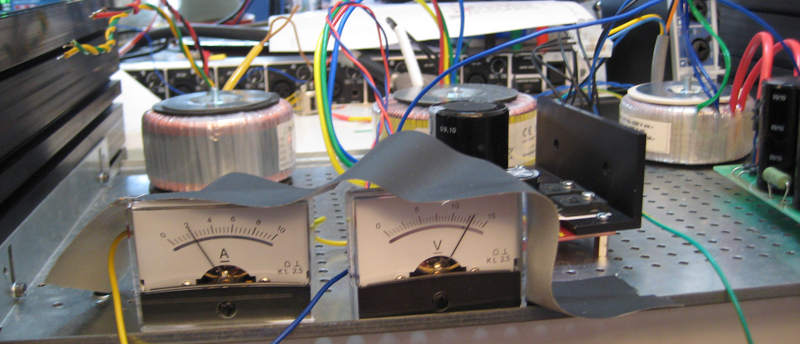
PSU:

psu.jpg


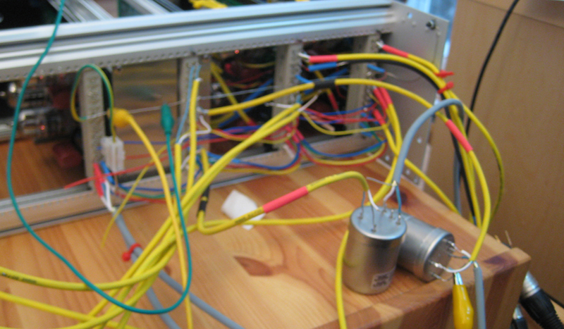
Rear of my test rack (sorry, a bit blurry):

test-rear.jpg


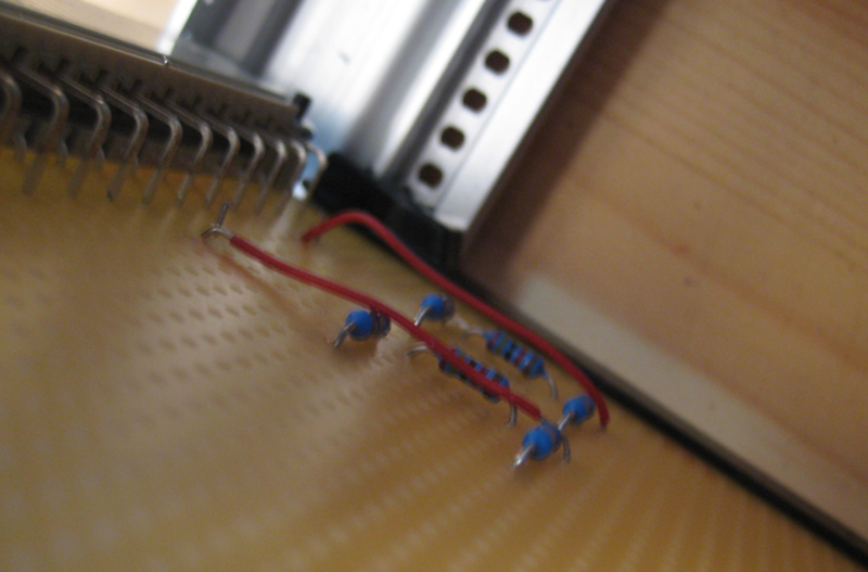
Dummy load for the EQs, I currently don't have any in 3 RU size:

dummy-load.jpg


anjing said:
... If don't mind sharing how you achieved the regulated HTR-PSU...

I opened my wallet and bought a ready-built module from THEL
http://www.supertube.de/HR10A/HR10A.htm
Since my time is limited I decided to buy a ready-built regulator. It thwarts the DIY idea a bit but hey...


@Holger 10A should be enough!....your building a diy tube mixer i doubt buying the power supply thwarts anything! Are you gonna keep the voltage and amp meter in you final power supply?
Those two sisters look nice. I'm thinking of getting some too.
Thanks for the pics!

Pierre
 
All this is inspiring!
Still waiting for a couple of parts and then, let the soldering begin!
I'm going with the Cinemag input transformer and the recommended Carnhill for the output as I'm just building one channel plus ps for testing.
Based on the sound samples, I'm expecting great things.
As I only record myself for voice overs, audio books and instructional videos, I really don't need a mixer but if I was producing anything more, I think I would go for six channels plus the Pultec EQs and Ian's possibly upcoming compressor.
But all of my clients simply want a clean voice track.
They add all the production elements at their end.
I'm certain I'll have more questions as my build gets underway.
Thanks to all the great people offering assistance here!
 
Holger said:
I opened my wallet and bought a ready-built module from THEL
http://www.supertube.de/HR10A/HR10A.htm
Since my time is limited I decided to buy a ready-built regulator. It thwarts the DIY idea a bit but hey...

Just one word of caution. I expect that if you take any where near the full 10 amps from this that it will need bolting to a substantial external heatsink. Don't forget that, with heater elevation, this heat sink sits at about +75 volts so the heatsink must be insulated from the chassis (which gets connected to 0V at the PSU).

Cheers

Ian
 
@Holger,
The light bulb isn't turning on for me with your PSU. Are you just regulating the heater voltage? What is the PCB to the right in your pic? What is your HT+ voltage?
I'm seeing the meter on the right in your pic reading 12V?

I'm sorry I'm a bit confused...

Dave
 
Looks like I'm going to throw my hat into the ring and build a 24 channel console using the twin line amp as the building blocks!!

The work you guys have been doing has inspired me to take this on. Looking forward to this adventure!
 
Hello Ian and the rest of us building this great project.
I have a few more questions.
1.  Does the red dot on the Cinemag CMMI-10PCA indicate pin 1 of the transformer as it relates to the board?
I'm assuming it does but you know assumption is a dangerous thing.
There's nothing about it on the Cinemag site and there are no numbers adjacent to the pins on the transformer.
2.  I'm a bit confused about the resistor ladder for the Grayhill gain switch.
I see the order listed in Ian's documents and the values.
Are the resistors laid out numerically from the left hand side looking at the board from the front side, left to right?
Or is the order reversed as per the note saying the lowest value resistor should be on the rightmost resistor position on the board?
3.  The 10k fader between the two amps, should it be audio taper, linear, log or?
4.  The little trimmer pots on the board are for fine level adjustment?
I have most of the components and have started stuffing, still waiting for my power transformer which is expected to arrive next week.
Thanks for all the help on this.
 
Hi Mike,

Welcome to the project.

1. The red dot on the cinemag is pin 1. This corresponds to the hole marked C1 on the PCB.

2. Unfortunately left and right depend on which way you look at the PCB. The assembly instructions are correct. The lowest gain resistor goes in the position marked P1 on the PCB. This corresponds to pin 1 of the switch.

3. 10 K log or audio taper is fine for the fader.

4. The trim pot is only needed on the second preamp to set the gain (marked GAIN2 on the PCB). You do not need to fit it to the mic pre  ( marked GAIN1 on the PCB).

Cheers

Ian
 
Holger suggested setting up a separate build support thread in the mixers/monitors section. I think this is a good idea so I have set it up. Please ask all your build related questions there. We will keep this thread for discussion of development and design topics.

Cheers

Ian
 
I have just completed the design of the twinlineamp PCB and ordered 30 boards. There is room on the PCB for two input transformers. The secondariness are brought out to pads so you can wire in faders or EQ etc.. I have also modified the heater wiring so that ECC99 tubes can be fitted instead of the regular 6922 output tubes. This makes it easy to reconfigure this PCB as a headphones amp.

Cheers

Ian
 

Attachments

  • twinlineamp.png
    twinlineamp.png
    55.9 KB · Views: 27
Hi Ian,

  I think i found a problem with the CMLI-15-15B input transformer we planned to use for the twin line input. I remember Dave confirming they were the same foot print as the CMMI-10PCA. There was a small mixup with my order and the CMLI15 was shipped seperately, even if i got them a while ago i just today had a closer look, anyhow to make a story short they are not the same footprint.
  I'm really sorry about that because you made the twin line pcb with information i gave you, and i was wrong. I will ask Dave about it, maybe he can make them with the same footprint...

Regards,

Pierre


Attachments

  • CMMI-10PCAvsCMLI-15-15B.jpg
    CMMI-10PCAvsCMLI-15-15B.jpg
    173.4 KB · Views: 15

Latest posts

Back
Top