EZ Tube Mixer

GroupDIY Audio Forum

Help Support GroupDIY Audio Forum:

This site may earn a commission from merchant affiliate links, including eBay, Amazon, and others.
Dave,
If you use CrossOver there is a chance you may be able to get Corel Draw 11 to run without Parallels (e.g. emulated). It is in the list of "supported" Applications for CrossOver, I can't seem to find a version of it though. It is fairly old software.

In answer to your question, I use Corel X5. Corel X6 is the latest version, but I don't really see the point. All you need is the contour tool and HPGL functionality.

All the best,
Braeden
 
Hi Ian!
        I noticed the nice srs divider you got! Do you think it is compatible with schroff subracks?
I was also wondering what type of header would fit the J9 and J10 on the backplane to daisy chain the busses?
Btw  i built a channel with the cinemag CMMI-10PCA input transformer and i really like what i hear!

Salutations from Montréal,

Pierre
 
anjing said:
Hi Ian!
        I noticed the nice srs divider you got! Do you think it is compatible with schroff subracks?

Probably not. Although the front panels, PCB sizes and connector positions are all the same, each manufacturer uses different shaped extrusions and the side panels into which they fit all have fixing holes in different positions. I know because I tried mixing parts from two manufacturers and they just would not work. When I checked the data sheets I saw one had fixings on a 10 mm pitch, one on 12 mm and another on 15 mm.

I was also wondering what type of header would fit the J9 and J10 on the backplane to daisy chain the buses?

At the moment I don't think there is one. I found some 0.2 inch spacing headers and foolishly assumed that a 2 row version would have the rows 0.2 inches apart. They don't, they are 0.1 inches apart. So right now the best bet is to use a pair of single row 0.2 inch headers like these:

http://tinyurl.com/b2fuxq7

Or hard wire them. I need to think of a fix for this for the next version.
Btw  i built a channel with the cinemag CMMI-10PCA input transformer and i really like what i hear!

Salutations from Montréal,

Pierre

Excellent. How does it compare to the other channels you have built?

Cheers

Ian
 
Ian,
So Eric and I are trying to get our power supply requirements sorted out and I was wondering, if I wanted to power 20 cards from one supply and could have a custom transformer made, what would I need to change on the HT350 for the larger current draw?

Dave
 
Hi Ian,
I kind of expected the dividers would not work...the divider kits from schroff eats 2hp in the process so it is no good.

Thanks for the info on the headers, i found a molex with the same pitch. http://ca.mouser.com/Search/ProductDetail.aspx?R=10-08-5061virtualkey53810000virtualkey538-10-08-5061

I only tried it a bit, but i feel i prefer the cinemag to the sowter. I recorded some jazz drums with just an akg 414 and it sounded detailed and rich right away. I have to make some more recordings before i have a more definitive opinion. The first impression was just very good.

Were are you at with the demonstration mixer?

Regards,

Pierre
 
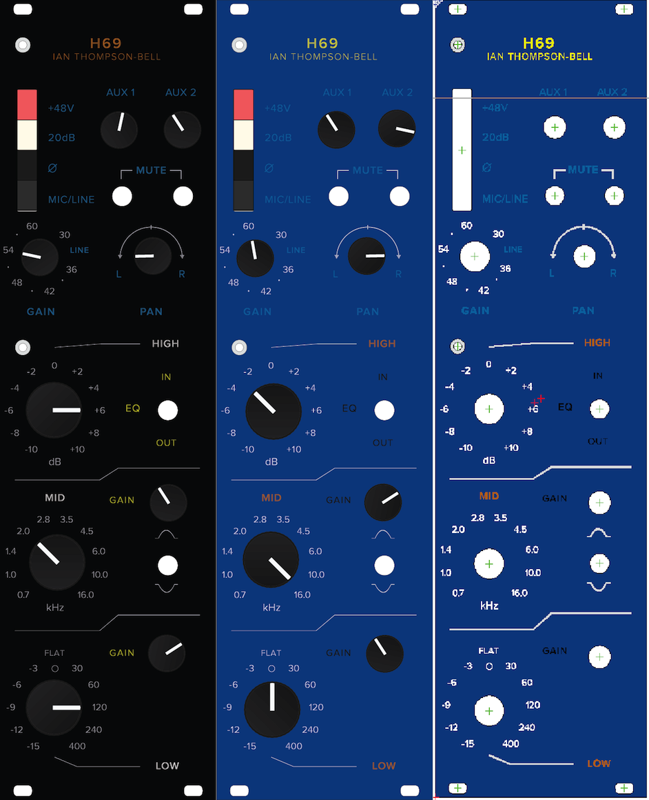
I've made some progress. The FPD file has been created for the H69.
I designed it so the person using it could choose whatever colours they want for various parts of the panel (I tried to illustrate this with my deliberate use of ugly colour combinations).

Be warned that the more colours you choose, the more the cost and the greater the lead time.
The cheapest option you can do is $57.29 ex. shipping.

This is without any infill and a standard anodised black front panel. You can of course save $1 by choosing the clear anodised but you'll be struggling to see the text ::)

IXyjqA1.png


Just so you know I'm not slacking off - proof of the FPD design on the far right.

Sorry to destroy your thread like this Ian!

Braeden

P.s. I'm still sorting some things out (the overlay seems a little askew at the moment), I think this is the result of my crappy version of Corel.
 
wave said:
Ian,
So Eric and I are trying to get our power supply requirements sorted out and I was wondering, if I wanted to power 20 cards from one supply and could have a custom transformer made, what would I need to change on the HT350 for the larger current draw?

Dave

20 boards will draw about 200mA HT current. As a rule I aim for a 10V drop across each series resistor on the HT350 which means the resistor value needs to be about 50 ohms - 47 ohms will do. However, each resistor will dissipate about 2 watts of heat so they will get pretty hot. You would need to use 10 watt rated types. The HT350 board was not really designed to run 20 boards - about 10 is really its design limit. Beyond that, the resistor dissipation starts to get rather large and the smoothing is not as good. Bottom line is I would recommend you use a pair of HT350 boards each fitted with 100 ohm 10 watt resistors and each supplying 10 boards. You still only need one rectifier and one transformer secondary winding. I will draw a sketch of how to wire them together and post it here.

Cheers

Ian
 
anjing said:
Hi Ian,
I kind of expected the dividers would not work...the divider kits from schroff eats 2hp in the process so it is no good.

That's a pity. I would have thought schroff would have been better than that.


They look good - you can always rely on Molex!!

I only tried it a bit, but i feel i prefer the cinemag to the sowter. I recorded some jazz drums with just an akg 414 and it sounded detailed and rich right away. I have to make some more recordings before I have a more definitive opinion. The first impression was just very good.

I guess the good thing is there is a choice of three transformers. I was recently asked if it would be possible to use an OEP A187A14C transformer which can be wired as a 1:8 mic transformer. I have never used OEP and I could not find this model at the normal UK distributors so I asked for a quote via their web site. They asked me how many I would use and what it would be used in and I said I just wanted one to try out in a prototype. I don't know if they found out some more about me but the next thing I know was I got an email saying their Technical Director had said they would send me a sample for free!  It arrived this morning. It's rectangular and about three quarters the size of the Jensen. I will try it out and if it performs well I'll look at modifying the PCB layout to accommodate it. I still don't know how much they cost.

Were are you at with the demonstration mixer?

Regards,

Pierre

Working on the boards to go in the mixer right now. I need to build another Helios and a  Pultec EQ board. If the OEP transformer works out I'll fit it to one of the channels, then I 'll have four different mic transformers in there, Sowter, Jensen, Cinemag and OEP.

Cheers

Ian
 
Hello Ian!

Maybe I'm not looking in the proper place but I haven't been able to find values for components on the HT power board.
I know the diodes are 1N5408s.
What are resistor values and watt ratings for R1 through R5, please?
And what is the voltage rating for the four 470uF electrolytics and the 47uF and the 100nf capacitors?
This board is looking for a 240 volt input, correct?
And the 75v output is designed to be used for the 48v phantom with appropriate dropping resistor?
Sorry for the questions but I haven't actually built anything for decades, just have done repairs to existing equipment.
 
Mike,
Have a look at this:

http://www.ianbell.ukfsn.org/EzTubeMixer/docs/power/HT350cct.png


Dave
 
No worries. There's a lot of them (very good documentation). I go to Ian's site 50 times a day to look at stuff I've looked at 100 times before Haha!

Dave
 
Hi Mike,

Dave has answered most of your questions; I'll just add a couple of comments. The PCB is designed to take 1N5408 diodes but  later discovered these are overkill and regular 1N4007 types work just as well.

The 75V output is for heater elevation. In most tube designs, one side of the heaters is connected to ground. The Euro channel card uses an output stage that has the cathode of one tube at about half the HT supply voltage. In order not to exceed the tubes heater to cathode voltage specification you have to make sure the heater voltage is also elevated above ground so the heater to cathode voltage is kept within spec. The 75V point does this and should be connected to one side of your heater supply. The other side of the heater supply should be left floating. You must not connect the heaters to the HT 0V.

Cheers

Ian
 
Thanks again, Ian and Dave.
Tube designs were more basic back in the '60s.
You tried to make things work with as few components as possible and tried to use components you could scrounge from old and surplus equipment because radio station owners hated to spend money (and that's even truer today.)
As I mentioned, this is the first real build I've attempted in years but I've been fixing gear all my life.
It's just that everything is so much smaller these days (or maybe it's just my old eyes!)
But I have a board vice with magnifier attached and have just purchased a small tip soldering iron.
Parts are ordered and are starting to trickle in.
Luckily, some are available locally and are not expensive.
 
I just measured the inductances of the windings of the OEP A187A14C I mentioned a few posts back. The secondary inductance is around 240 Henries and each primary has an inductance of about 4.25 Henries. With the primaries wired in parallel it forms a 1:8 step up mic transformer. Under these conditions the primary inductance is about 2.2 Henries which at 20Hz has an impedance os just under 300 ohms which will give a 1dB drop with a 150 ohm source. So it will be fine with condenser mics with output impedances around 50 ohms but perhaps a little bass light with dynamic mics.

I think it is definitely worth trying out in the Eurochannel amp.

Cheers

Ian
 
I cleaned up the mouser bom. It is for one eurochannel and inludes all but, the pcb connector, alps pushbuttons, grahill switch and printed board bracket. If anyones needs those part numbers i'll be glad to share as well.
The bourns 10k trimmers needs one leed to be bent in order to fit. Same goes for the panasonic 4.7uf 450v cap.
https://ca.mouser.com/ProjectManager/ProjectDetail.aspx?AccessID=46a9e50c95
Please double check before you place the order, it looks well and i double check a few times but you never know!
Also the relay for the di is included in the bom but i did not use it myself, i added it using the part number supplied by Ian in the assembly notes.

 
Thanks Anjing!

I've now got all my parts ordered for the one channel I'm building to try first.
Transformers coming from Cinemag and Carnhill.
Hope your build is going well!
 
Back
Top