There's a lot of chasing ghosts in this thread but a few good suggestions.
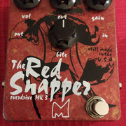
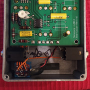
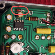
Dirk's schematic is clearly wrong for this pedal: The photograph of the inside of the pedal for repair has a 1044 charge pump. There should be a 12V Zener diode in this version because the maximum voltage for the chip is 12V. However, if your friend really did plug in a 12V supply, the charge pump would survive and they would just get 24V instead of 18V distributed throughout the circuit, which is unlikely to blow up any parts.
Many guitar pedals now use a 1N4001 or similar in series with the voltage supply to protect against reverse polarity. The old technique of strapping the 1N4001 across the power pins is from the days when the only thing it would blow up was a battery, not a wall wart, and people didn't want to lose the precious 0.6V of battery power by connecting it in series. Almost all guitar pedals that use a charge pump use a Zener for overvoltage protection, in part because it's what everyone else does, in part because it's cheap and it works just enough, and in part because ... well, honestly I'm not totally sure everyone even knows that voltage regulators exist ...
Anyway, here's a simple procedure for fixing a guitar pedal you don't have the schematic for:
1. Hook up your DC meter to ground and the tip of the power jack. Plug in a normal 9V supply and check that you have 9V across the DC jack. If you don't, put your meter on continuity and start locating the parts connected to the DC jack. You want to check for the following: (a) shorted electrolytics, (b) burned out diodes (e.g. a zener that's been fried by overvoltage will have let the magic smoke out), (c) A dead charge pump chip.
2. Here's the datasheet for the charge pump: http://ww1.microchip.com/downloads/en/devicedoc/21348a.pdf. If you need to see one in use, the Madbean Road Rage is a useful enough schematic: https://www.madbeanpedals.com/projects/_folders/BreadBuddies/schematics/RoadRage2019.gif. Check the voltages on the charge pump; if it's working, the easiest thing to check is that pin 5 is -9V. Post the voltages on all the pins of the 1044.
3. There would be a pair of rectifier diodes if the charge pump were being used as a voltage doubler, and I don't see them in the picture; this leads me to believe that it's being used for a bipolar supply on the 4558. Take voltages (and post them) on the 4558. You're either going to have something like 1,2,3,5,6,7: 0V, 4: -9V and 8: +9V or something like 1,2,3,5,6,7: +9v, 4: 0V, 8: 18V. If you have voltages on the charge pump and NOT on the 4558, switch to continuity again and start backtracing. The bottom line is that it's not a very complicated circuit. The distortion is the two back-to-back diodes next to the 4559, and the resitors and capacitors there are tone shaping and gain setting. About a third of the capacitors on the board are for power filtering, and there's what looks like the parts for a simple tone control in the bottom left (for the bite control). The axial just south of the power supply is the cut cap, probably 10nF. All of those parts are going to be fine.
The worst possible thing that's happened is that the 1044 is blown and you have to replace it. It happens a lot. Notice that the road rage uses a 1054 instead --- we all switched over to those after getting tired of everyone asking why their Klone/whatever blew up. The 1054 can take 15V and survive short exposure to 18V inputs, it's just MUCH less likely to blow up if someone plugs in the wrong thing. Anyway, if you have to order a part, you might as well pay an extra dollar for the better one.


