Line mixer (active)

GroupDIY Audio Forum

Help Support GroupDIY Audio Forum:

This site may earn a commission from merchant affiliate links, including eBay, Amazon, and others.
[quote author="NewYorkDave"]Ah, grasshopper, if you leave out the panpot, then you have to readjust the level and gain structure throughout. The panpot circuit has 6dB minimum loss, and the rest of the circuit was scaled to harmonize with that.

It's a "simple" design, yes, but there's a reason for everything in it.[/quote]

Readjusting the level and gain structure is more than only changing the value of R2 right? Don't tell me, I'm going to build the thing and find it out by trial and error.....my way of learning things.
 
I have one qustion though.....How much buffering can one opamp provide?

It depends on the opamp, and what kinda of load it has to drive. you need to figure out the equivalent value for all of the series/parallel resistances that follow it (including the feedback resistor).

Something cheap like a TL07x might not want to drive less than maybe 2K before it gets unhappy. A 5534 will do 600 ohms, but not much less. Various discrete/hybrid amps can drive below 600...Hardy rates the 990 to 75 ohms, and 2520's are similar.

This is one of those applications where discretes really come into their own.

In this case it's buffering two aux sends and the master/groups but is it also possible to make the channel assignable to a group AND the master?

In addition to the ways Dave mentioned above, one way would be to move the buss feed resistors in front of the assign switches, and make it so the assign switches switch those resistors between the panpot and ground (Soundcraft 600 is one example of this...schems downloadable from Soundcraft). That channel feed to the buss then floats when not assigned.

This keeps the panpot load constant, but does it at the expense of changing the buss source impedance as channels are added/removed. This means that the gain applied by the summing amp will change as the load changes, altering the gain-bandwidth product. With a really high GBW amp, it's bandwidth externally constrained with a small feedback cap, and not too many channels, this might not matter to you.

Dave - your new channel schematic look like what I'd been working on for the AC-coupling and optional ground sense resistors. A question about one of the changes. I notice you changed the aux pots to 2.5k, and added series resistors in fron of them. Did you change the pots so they'll be a little more immune to the loading of the 10K buss feed resistors, then add the 2.2K series resistor to keep the overall load of the aux sends a bit higher? This also makes a roughly 6dB loss to the aux busses, so their gain structure followes the stereo buss better, right?
 
"In addition to the ways Dave mentioned above, one way would be to move the buss feed resistors in front of the assign switches, and make it so the assign switches switch those resistors between the panpot and ground (Soundcraft 600 is one example of this...schems downloadable from Soundcraft). That channel feed to the buss then floats when not assigned. "

That definitely works. You've already alluded to it, but to expound a bit: there are two schools of thought regarding how to go about switching channels off a buss. One maintains that the best way is simply to disconnect the feed resistor; the noise gain of the summing amp goes down as channels are de-assigned, and this is seen as a Good Thing. Others don't like the idea of the "sound" of the summing amp possibly changing, depending on the number of channels assigned, and instead opt for schemes to keep noise gain the same regardless of the number of channels on the buss. I think both are valid points, so I don't really take sides in that debate.

"A question about one of the changes. I notice you changed the aux pots to 2.5k, and added series resistors in fron of them. Did you change the pots so they'll be a little more immune to the loading of the 10K buss feed resistors, then add the 2.2K series resistor to keep the overall load of the aux sends a bit higher? This also makes a roughly 6dB loss to the aux busses, so their gain structure followes the stereo buss better, right?"

Exactly--on all three counts.
Another reason for the series resistors was to minimize the possibility of clicks on the pre- or post-fader busses when switching auxes--although admittedly, this is not likely to be a huge problem anyway, since the impedance looking back into the buffer outputs is very low as it is.
 
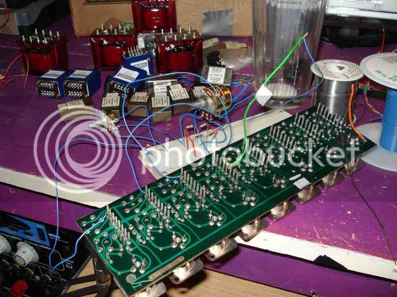
well Instead of fixing up my soundcraft board like I had intended I ripped the thing completely apart.

Fancy that all the faders are 10K perfect for NYD's active mixer. I have the rest of the parts laying around so I'll whip a rough breadboard version in a couple of days.

I just had a little 101 self taught panning lesson and tried it out in protools.

Here's an input section of my S.C. board I'll use. All balanced neutrix connections.

DSC02009.jpg


-richie
 
[quote author="capnspoony"]well Instead of fixing up my soundcraft board like I had intended I ripped the thing completely apart.
[/quote]

Now THAT's the spirit! Looks like it's going to be a very nice project with all that iron you have there laying around......
 
yep!

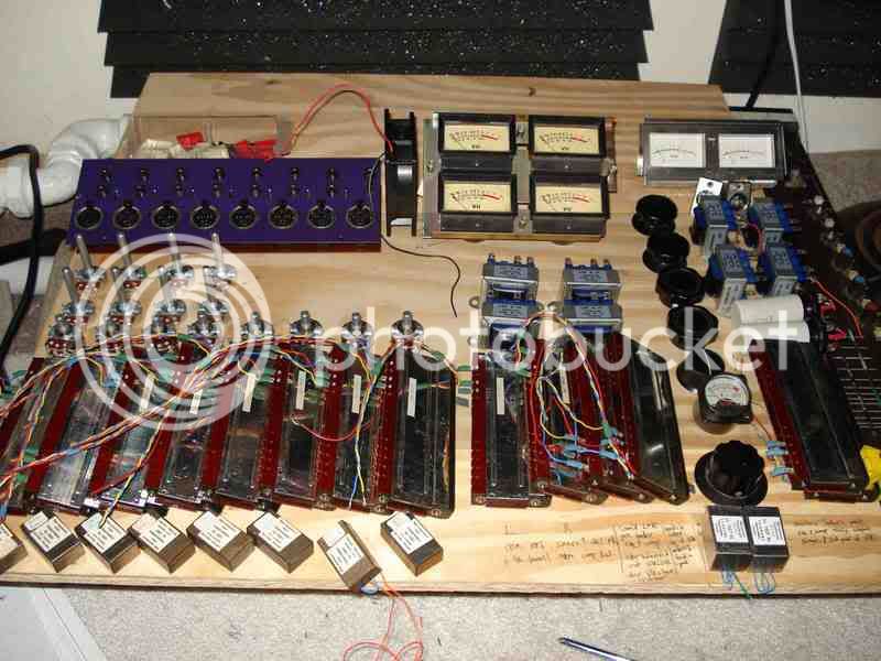
It won't be laying around for much longer .. I visually planned out my board last night. I'm building this mainly for drums.

It will be 8 channels. The first four will have L & R aux sends for a reverb stem mix for drums. Then Everything will be dumped into the first master fader section just like in NYD's plan. After that I have a gssl and another NYD passive eq built for my stereo out. I will be able to patch the eq and compressor in any order. This will feed into a final makeup gain section with two 425P amps. This make up section will be for both the eq and the compressor.

I'm going to build the Input channel section today and see how that goes.

DSC02012.jpg


Those transformers on the input are from tommyjones and they sound great. I did a little breadboard test with them last night in protools.

-richie
 
Nice layout! You can practically see it working :grin:

I'll be building a summing mixer with those Lundahls as well. Good to hear they're nice sounding.
 
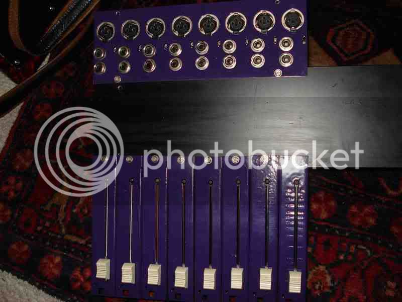
This was a lot of work but my input section is done minus the aux sends.

I breadboarded the master section up to test it out. So far so good. Each channel also has a direct out and return. I haven't drilled the panning pot holes yet.

DSC02078.jpg


-richie
 
[quote author="Wavebourn"]Richie, where do you get such nice faders?[/quote]

[quote author="capnspoony"]well Instead of fixing up my soundcraft board like I had intended I ripped the thing completely apart.
[/quote]
 
I've spent more time hacksawing than soldering. :twisted:

Wavebourn:

I might have 2 pairs left. Let me know if you'd like a pair. They'll be great for this project since they are 10K.

-richie
 
[quote author="capnspoony"]
Wavebourn:

I might have 2 pairs left. Let me know if you'd like a pair. They'll be great for this project since they are 10K.

-richie[/quote]

Thank you Richie, I mean if supply of them is available. :)
 
Ok, I got my Lundahl trasformers and started on a stereo channel on Vero board with place for both discrete and normall opamps. I got a Lab PSU from ebay, so the experimenting can begin. I find this all very exciting :grin:

30j77rk.jpg
 
All right... New year, new deal: I'm going to be re-drawing all the schematics to bring them closer to my original concept. I want to recapture the interest in this project that I had lost when I became sidetracked by other people's wish-lists.
 
[quote author="NewYorkDave"]All right... New year, new deal: I'm going to be re-drawing all the schematics to bring them closer to my original concept. I want to recapture the interest in this project that I had lost when I became sidetracked by other people's wish-lists.[/quote]

Great :thumb: I understand that it's not very rewarding when people add wishlists without even trying to build any of it.
My veroboard project now has almost all the components on it in sockets so I can experiment a little....
Thanks again!
 
All right, I've been thinking about various ways to handle the bussing and mixing. I wanted to post a sketch of this idea before incorporating it into the updated schematic; let me know if you see any flaws that I may have overlooked.

mxingidea.png


This is for assignability to a main L/R buss and two subgroups. It could be increased to main L/R plus four subs by changing the 22K resistors to 33K.

The reason for the unusual assignment switching is twofold. First, the panpot wiper needs to be loaded with about 10K to give the correct "law." Second, for my own perverse reasons, I don't want the noise gain of the mix amp to change as channels are assigned to/removed from the buss.

I used a variation of the differential mixing setup shown in Fred's PDF, with a little tweak to minimize input offset voltage--which may not be anything to worry about, anyway, since the amp output is capacitively-coupled.
 
PS: In the drawing, I forgot to include small (<100 ohms) resistors in series with the mix amp outputs and inverting inputs, to enhance stability. It's an old trick but an effective one.
 

Latest posts

Back
Top