C.B. - Boudio
Well-known member
Thank you very much!
I think I will try to build it this summer (or at least start to do so).
I think I will try to build it this summer (or at least start to do so).


Bravo Gyraf, this works! By using the existing side chain fed from the input, I can get some trouble free compression. The 6DT8 tube gives a gain of 35 which does not generate enough -ve voltage, but I can reconfigure the tubes for more gain. I'm not sure how I can keep the channels isolated either, with a single side chain, but maybe someone has some ideas on that. A good days work!..or simply run it feed-forward..?
Ala RCA BA-6B.Usually you connect the attack before the release.
But this has the disadvantage that the attack setting will influence the threshold, because you create a voltage divider. I once reversed these controls; first release and then attack.
In this case the controls don't influence each other much, because the attack resistors are usually (much) smaller than the release resistors.
Something else I usually do is to use two time constants, a small capacitor and a bigger capacitor in series with a bigger capacitor in parallel with the small capacitor. The effect is that for short peaks you get a fast release (the bigger capacitor is not charged yet), but for signals with a longer duration, the bigger capacitor will also be charged resulting in a slower release.
I found that this approach makes a compressor sounding more 'musical' (if that is a correct term here...)
Also known as 'program dependent release', 'composite release' or 'auto release'
Following your development with interest!
Interesting.Something else I usually do is to use two time constants, a small capacitor and a bigger capacitor in series with a bigger capacitor in parallel with the small capacitor.
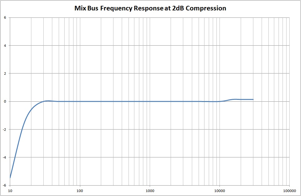
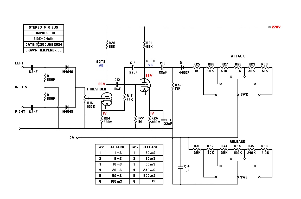
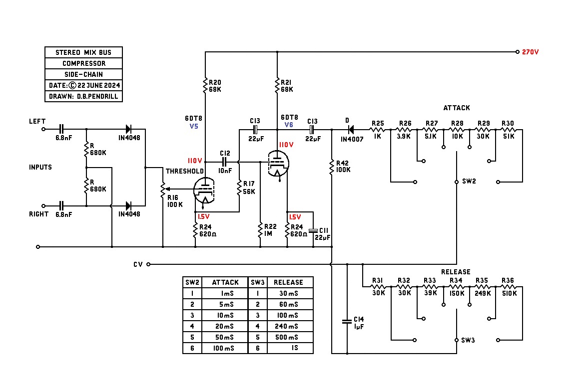
I have made a few adjustments to improve the performance of the side chain.
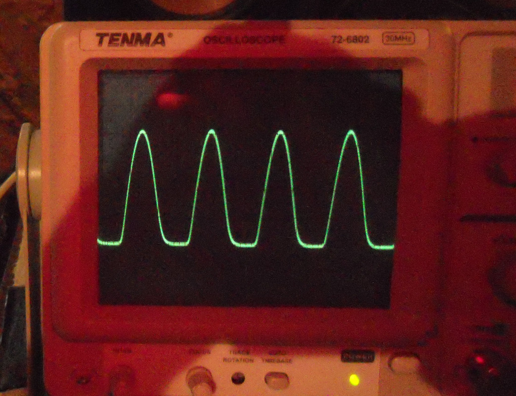
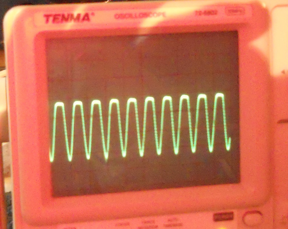
The input to either channel needs to be about 0dB or 1.25V, this gives sufficient drive to the side-chain to generate the required negative voltage for compression. With a sine wave input to both channels of the mixbus you get a train of pulses going into the first stage of the side-chain amp:-
The output to the second stage becomes the inverse:-
This gets rectified to -ve DC depending on the input level and threshold from zero to as much as -20V.
best
DaveP
The output is the negative Control Voltage CV to the grid resistors of the input tubes.
I don't see why the side-chain could not be made with transistors if you like, but I prefer working with tubes myself.
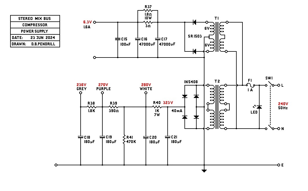
The power supply is made with Standard Transformers. B+ is 2x115/2x115, heaters are 2x6/2x115.
Best to read the whole thread first. This compressor will only give around 6dB which will be fine for its intended use for the mix bus. You sound like you might need more than that and there are better designs out there than this.
With a simple power supply all you have to worry about is 50Hz and a few harmonics. Switch mode power supplies are only for the brave.
Best
DaveP
Enter your email address to join: