Neumann U67 Clone : D-U67 Tube Microphone Build Thread.

GroupDIY Audio Forum

Help Support GroupDIY Audio Forum:

This site may earn a commission from merchant affiliate links, including eBay, Amazon, and others.
tskguy said:
It really truly dumbfounds me how you guys are spinning all this comparison with different capsules!!
Please at least use the same capsule while doing these comparisons!! Or none at all! Remember 90 percent of the sound of a mic is the capsule. GEESH!!!

I totally agree.
 
jpertusi said:
...anyone...  Bueller?

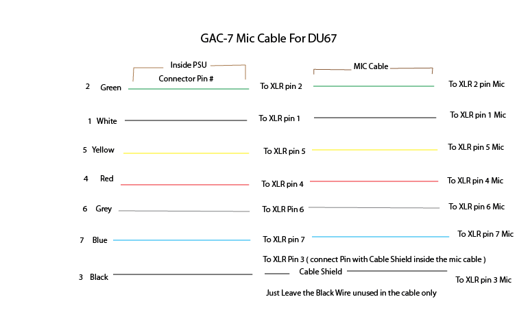
"Do the numbered locations on the PCB (1, 2, 3 on the XLR out and 1 thru 7 on the MIC out) correspond to the pin numbers I should be connecting them to on the connectors?"

Is there a pinout for this section of the PCB?  I just want to be extra careful here...

Also... just got my bv12's!!!  Thanks Max!!!

Thanks as always gang.

the first Link on page 1 in the thread contains Precious information for this build including this file here ,
do not hesitate to consult and download the Build Folder from this link, 
Best,
dAN,


58d02819940c1.gif
 
Studio Mollan said:
I could tell instantly that max's trafos were darker from your first speech tests and I liked it. That's why I got two ami and two max kits. To have two flavors at hand. But in use the difference is quite brutal.. I will try to mod C17 to get what I want. I like them dark sounding, I'm not looking for a hifi thing here, only to get some more hi frequencies.

I've also noticed that my DU67 mics with Max's trafos are very dark sounding, requiring Hi EQ lifts depending on the sound source.  I'll be following your explorations as regards C17 with keen interest.  Thanks for this.

 
Jim50hertz said:
Studio Mollan said:
I could tell instantly that max's trafos were darker from your first speech tests and I liked it. That's why I got two ami and two max kits. To have two flavors at hand. But in use the difference is quite brutal.. I will try to mod C17 to get what I want. I like them dark sounding, I'm not looking for a hifi thing here, only to get some more hi frequencies.

I've also noticed that my DU67 mics with Max's trafos are very dark sounding, requiring Hi EQ lifts depending on the sound source.  I'll be following your explorations as regards C17 with keen interest.  Thanks for this.

Ill kerp i posted. Both transformers measure pretty much identical so i guess the difference must be the actuall winding, material etc. Im experimenting on this in breaks in between sessions so it might take a while.
 
Studio Mollan said:
Ill kerp i posted. Both transformers measure pretty much identical so i guess the difference must be the actuall winding, material etc. Im experimenting on this in breaks in between sessions so it might take a while.

I appreciate it and am in no rush.  I've subscribed to the thread and will watch with interest.
Peace
Jim
 
Studio Mollan,

I'm trying to track down a low output (5db) and have pretty much ruled out everything other than the transformer. I purchased two t67's and had A few questions for you:

I was going to play devils advocate and say "maybe the bv12 is normal and the t67 is hyped" but I have shot my mic out against two original untouched u67's and despite being 5db down, I'm getting the exact EQ as found in the original.

Do you get the same output levels from all four mics? If so, have you shot them up against an original?

Do your resistance tests across all transformer show the same ratio's?

Do you use the same coupling capacitor across all four mics and what material / values are they?

Cheers.

J
 
JessJackson said:
Studio Mollan,

I'm trying to track down a low output (5db) and have pretty much ruled out everything other than the transformer. I purchased two t67's and had A few questions for you:

I was going to play devils advocate and say "maybe the bv12 is normal and the t67 is hyped" but I have shot my mic out against two original untouched u67's and despite being 5db down, I'm getting the exact EQ as found in the original.

Do you get the same output levels from all four mics? If so, have you shot them up against an original?

Do your resistance tests across all transformer show the same ratio's?

Do you use the same coupling capacitor across all four mics and what material / values are they?

Cheers.

J

Hi!
The levels are within ca 1db across the four microphones but I have not had a chance to compare with an original. My gut feeling is that the t67 is more like the original but not having tested it's no more than a gut feeling. The transformers measure pretty much identical across the windings which is a bit strange as they sound so different. I'll try to do more measurements next week and will post here. As the shelving point from where the two versions differ I'm feeling confident it can be calibrated with C17. As I said earlier a hi shelf plus 6db from ca 1500Hz made the two almost identical. That seems to correspond with a sweep of the amplifier seen earlier in this thread.
I'm using the cap from the BOM but actually just today I looked through my shelves and found some alternatives. All vintage. Films/PIOs. Looking forward to hear what the will do to this microphone. From my experience with other builds the difference will be subtle changing caps though. The brand or type of cap can not be causing the amount of dullness I'm experiencing with the IOaudio transformer.

Just to clarify. I am absolute positive that the IOaudio transformer is not poorly made or bad sounding. I'm pretty sure the circuit needs alterations to suit it though.
/
Emil
 
poctop said:
is your R12-R13 Polarisation Divider well matched ,
you should be getting 55V at least for the backplate , it has to be measured before the capsule Charging resistor tough,
but this would not explain a 4db difference
keep us posted,

Best,
Dan,

Hi Dan,

Cheers for answering this, i never saw it.

I don't know what you mean if they are well matched? I used the resistors from mouser in the BOM.

It would seem that i am 10 volts (20%) down at the divider though, I'm measuring using a 30meg capable Fluke 115.

You don't think 20% is a big enough difference to create 5db down on output?

Cheers

Jess
 
JessJackson said:
poctop said:
is your R12-R13 Polarisation Divider well matched ,
you should be getting 55V at least for the backplate , it has to be measured before the capsule Charging resistor tough,
but this would not explain a 4db difference
keep us posted,

Best,
Dan,

Hi Dan,

Cheers for answering this, i never saw it.

I don't know what you mean if they are well matched? I used the resistors from mouser in the BOM.

It would seem that i am 10 volts (20%) down at the divider though, I'm measuring using a 30meg capable Fluke 115.

You don't think 20% is a big enough difference to create 5db down on output?

Cheers

Jess

I had a Diode Current Regulator in one of my original 87 that burnt out and i was getting about 30V polarisation and the output did not change that much but this is from far away in my memory
but at this point it is hard to tell,  i might be affecting the sensitivity but at wich point is hard to predict is the 2 resistor are well match wich they should from the BOM you should have pretty much something like 56-58V easilly you might want to recheck values and make sure you can actually compare those as i never had one below 56V,
how much voltage do you get from the noe R15-R13-R16 , I will try to check on the mic here and confrim with you over next weekend,
BEst,
DAN,
 
JessJackson said:
Studio Mollan,

I'm trying to track down a low output (5db) and have pretty much ruled out everything other than the transformer. I purchased two t67's and had A few questions for you:

I was going to play devils advocate and say "maybe the bv12 is normal and the t67 is hyped" but I have shot my mic out against two original untouched u67's and despite being 5db down, I'm getting the exact EQ as found in the original.

Do you get the same output levels from all four mics? If so, have you shot them up against an original?

Do your resistance tests across all transformer show the same ratio's?

Do you use the same coupling capacitor across all four mics and what material / values are they?

Cheers.

J

Ok so i ran some tests. Replaced the Output cap with vintage PIO (Erofoil) on the IOaudio builds and Bosch PIO on the T67's. Both a lot smoother and less agressiv en the upper mids and air bands. Can really recommend you guys to experiment with this!

As for the transformers:
I meassured both and contrary to my earlier post they do differ. Possibly enough to cause the HF issues I've been writing about.
AMI:
Winding_
1 655r
2 26r
3 35r
4 35r
5 26r
6 635r

I/O-Audio
Winding.
1 1035r
2 42r
3 18r
4 1035r
5 42r
6 18r

They are not pin compatible. I don't know which windings do what but the 18r on the I/O audio is pretty off. If they are to share their relations between the windings i guess the 18r should be somewhat higher, as go for the 42r.

Im starting to think that changing the C17 cap wont change the amount of HF in the feedback loop only the point from where it starts subtracting. could adding resistance in series with C17 lift the high end maybee? If so what values should i start experimenting with. More resistance = less voltage to the Feedvack = less HF deduction. Am i right? (i could be way off here and will not be offended if you correct me. Please be gentle though..)  :)

/
Emil
 
I Do Have a Hand drawn schematic of the AMI T67 that Oliver provided a While Ago , i looking for the picture of it, i will post it here so you can refer this one per your winding scheme ,  as far as the IOaudio transformer it is very well documented on his WM,

stay tuned,
Best,
dan,
 
Emil,

Why are you swapping caps path before measuring the frequency response of the two amplifiers w/ the stock circuit and the different transformers???
If you made that simple measurement it would give you some solid footing to move forward from, as well as contribute some info to all the other people here interested.

All you need is to run a signal through the mic and measure the level coming out. Or download RMAA and make a nice sweep.
 
I meassured both and contrary to my earlier post they do differ. Possibly enough to cause the HF issues I've been writing about.

You're measuring DCR - which isn't the key thing for a transformer (an ideal transformer would have zero DCR). The DCR will be higher of a winding if the wire gauge is different or the total number of turns. But the ratios and inductance are much more important. The pinouts are different for the two transformers and the winding method, but each transformer has three windings. primary, secondary, and feedback. The primary will typically be much higher DCR than secondary since it has more turns. Both transformers look reasonable i think.
The EQ of the circuit is created by the amount of signal returned by the transformer through the feedback winding (hence primary/feedback turns ratio sets this level).
 
I was going to play devils advocate and say "maybe the bv12 is normal and the t67 is hyped" but I have shot my mic out against two original untouched u67's and despite being 5db down, I'm getting the exact EQ as found in the original.

What capsule are you using? This is going to dominate the perceived EQ.

5 dB down is almost half volume. The windings would have to be wrong by 50% amount. A wiring or measuring mistake is more likely.
Can you sweep the amplifier response of an original 67? That would be IMMENSELY valuable to this thread. Back a few pages I posted the sweep for a build w/ recommended components and bv12.
 
dmp said:
I was going to play devils advocate and say "maybe the bv12 is normal and the t67 is hyped" but I have shot my mic out against two original untouched u67's and despite being 5db down, I'm getting the exact EQ as found in the original.

What capsule are you using? This is going to dominate the perceived EQ.

5 dB down is almost half volume. The windings would have to be wrong by 50% amount. A wiring or measuring mistake is more likely.
Can you sweep the amplifier response of an original 67? That would be IMMENSELY valuable to this thread. Back a few pages I posted the sweep for a build w/ recommended components and bv12.

wich page again ,
Best,
dAN,
I might repost it here,
Thanks,
 
dAN,
No problem - here is the plot again.
This is built with recommended components and bv12. I used RMAA to make this freq sweep.
I am using a beezneez capsule - I do feel my mic is dark (but not in a bad way).
Hoping we'll get to the bottom of this! Not only bv12 vs. ami, but how close are we to an original. (and remember, the mic sound is usually 95% the capsule...)
Dan
 

Attachments

  • u67bv12_freqsweep.png
    u67bv12_freqsweep.png
    4.2 KB
dmp said:
dAN,
No problem - here is the plot again.
This is built with recommended components and bv12. I used RMAA to make this freq sweep.
I am using a beezneez capsule - I do feel my mic is dark (but not in a bad way).
Hoping we'll get to the bottom of this! Not only bv12 vs. ami, but how close are we to an original. (and remember, the mic sound is usually 95% the capsule...)
Dan

I was going to play devils advocate and say "maybe the bv12 is normal and the t67 is hyped" but I have shot my mic out against two original untouched u67's and despite being 5db down, I'm getting the exact EQ as found in the original.


I remember the one I sold that had a neumann capsule in it with the Max Bv12 and it was beautifully shinny or was it the aMI T67 version Jeez My memory plays me tricks,

AnyBody with a AMI T67 would like to comment regarding the IOaudio Bv12 ,
Or someone else that has both,

I really would like to see a sweep with the AMI T67

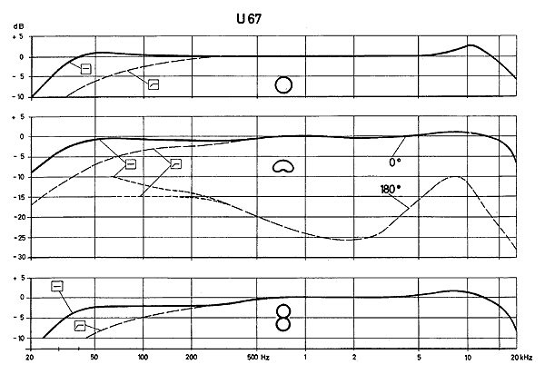
here a reference

58d02819940d4.gif


Let me know,
Best,
dan,
 
here a reference

Remember - those frequency plots are for the full mic with capsule in a anechroic (sp?) chamber. Not many DIYer's have the means to measure that.
The u67 had a capsule designed to boost high frequencies with an amplifier designed to roll off those same frequencies (see my plot), such that the overall freq response was flat. This design was intended to reduce noise. 
 
dmp said:
here a reference

Remember - those frequency plots are for the full mic with capsule in a anechroic (sp?) chamber. Not many DIYer's have the means to measure that.
The u67 had a capsule designed to boost high frequencies with an amplifier designed to roll off those same frequencies (see my plot), such that the overall freq response was flat. This design was intended to reduce noise.

Got it , this is the amplifier only sweep,  wich include the de-emphasis portion in the circuit to tame this particular section of the high end not to be confused with the sweeps with the capsule K67 with the high lift included,

Best,
Dan,
 
dmp said:
I meassured both and contrary to my earlier post they do differ. Possibly enough to cause the HF issues I've been writing about.

You're measuring DCR - which isn't the key thing for a transformer (an ideal transformer would have zero DCR). The DCR will be higher of a winding if the wire gauge is different or the total number of turns. But the ratios and inductance are much more important. The pinouts are different for the two transformers and the winding method, but each transformer has three windings. primary, secondary, and feedback. The primary will typically be much higher DCR than secondary since it has more turns. Both transformers look reasonable i think.
The EQ of the circuit is created by the amount of signal returned by the transformer through the feedback winding (hence primary/feedback turns ratio sets this level).
Hi, Im well aware I'm meassuring DCR. Dan actually taught me this only a few days ago. However the recistance over the windings translate to the turns ratio of the transformer if im not mistaken? Im positive this is the cause for the difference in the two transformers. But then again I'm also aware that I've been dead wrong on lots of DIY stuff in the past so me being the cause is not ruled out. =)
I did the meassurements cos a forum member asked about them and also the output cap tests. When i got an hour off ill try to do the sweeps.
 

Latest posts

Back
Top