Neumann U67 Clone : D-U67 Tube Microphone Build Thread.

GroupDIY Audio Forum

Help Support GroupDIY Audio Forum:

This site may earn a commission from merchant affiliate links, including eBay, Amazon, and others.
DCR will correlate in that the longer the piece of wire, the higher the DCR. The more turns, the more wire. But the ratio of DCR does not equal the turns ratio.
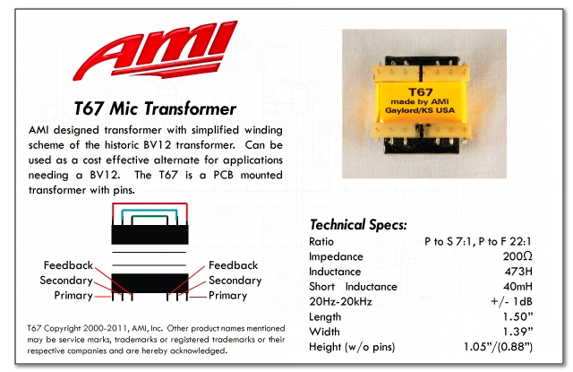
The primary to secondary should be 7:1, and the primary to tertiary should be 22:1, if I recall correctly. Simple way to measure this - you put a AC signal on one winding and take the ratio of the voltage amplitudes. I have a bv12 at home for my m269 build, I can measure the ratios later this week.
That being said, if the ratios ARE the same, the transformers could still lend different sonic signatures to the circuit due to the difference in DCR.
Thanks for helping with these discoveries. We're all interested to learn about the differences.
 
dmp said:
DCR will correlate in that the longer the piece of wire, the higher the DCR. The more turns, the more wire. But the ratio of DCR does not equal the turns ratio.
The primary to secondary should be 7:1, and the primary to tertiary should be 22:1, if I recall correctly. Simple way to measure this - you put a AC signal on one winding and take the ratio of the voltage amplitudes. I have a bv12 at home for my m269 build, I can measure the ratios later this week.
That being said, if the ratios ARE the same, the transformers could still lend different sonic signatures to the circuit due to the difference in DCR.
Thanks for helping with these discoveries. We're all interested to learn about the differences.

Thank you! This would be 100% impossible without this forum and its members contributions!
Well, breaking news. I did the amplifier test on both versions. Max'x trafo is DEAD ON!! Contrary to my presumtions thats aparently what they are supposed to sound like, given that theres nothing wrong in the cirquit. 15kHz is -10dB from 1kHz. 40Hz was actually louder but as i had my capsule on im assuming thats disturbance from my room.
The T67 did maintaind its level all across the spectrum so i guess theres something wrong in the feedback cirquit. Ill recheck that and return here when im done. Pretty strange that both of my t67 equiped builds both behave the same?

I need to compare my builds to a real Neumann 67. I still like the brighter ones though so im actually leaning on leaving them as they are.


DMP. Please remind me. What transformer did you use with the sweep you posted?

 
I'm wondering if the Beesneez K6 is a darker sounding capsule than a Neumann capsule. Harder to measure the capsule response. We'll just have to hope someone with a real 67 speaks up
 
dmp said:
I'm wondering if the Beesneez K6 is a darker sounding capsule than a Neumann capsule. Harder to measure the capsule response. We'll just have to hope someone with a real 67 speaks up

Indeed!! From what ive heard so far from this thread the clone is supposedly a bit brighter than the original..

Well i replaced C17 and still no HF roll of in the amplifier test. Very strange! I'm loocking at the schematics and its either C17 or the transformer itself thats bad. The transformer meassures correctly and the cap is brand new = I'm going crazy.
 
Seems like there must be a disconnection from the winding on the AMI. Have you double checked all the transformer connections? Maybe post some pics. Poctop can ID inconsistencies like lightning.
 
Thanks, Not sure how I missed that.  it even looks familiar so I mast have seen it when researching.  My poor brain.

Anyway, I got Mogami cable and the colors are different as follows:

Twisted pair (I assume this is audio signal):
White
Orange

Heavy gauge (I assume this is B+):
Blue
Green

Non twisted lighter gauge (I assume this is the heater):
Red
Purple

Braided shield


I'm going to look for a pinout for the PCB.

Thanks again.
 
Understood.

So I guess my problem is that I don't know what is on each of the outputs 1 through 7 on the PCB.


-JP
 
OK, I never saw the build folder... I'm on board now, thanks.

I still am not quite sure what I should use the second heavier gauge cable for (I assume 0V?)

This is what I've got from all that info (just to be sure):

1 and 2 are the audio out from the mic

3 is the cable shield

4 is the heater (heavy cable)

5 is B+

6 is the calibration

7 is 0V (the other heavy cable)


dmp said:
Seems like there must be a disconnection from the winding on the AMI. Have you double checked all the transformer connections? Maybe post some pics. Poctop can ID inconsistencies like lightning.
I have continuity all the way to C17 out from the feedback. and the transformer measures correct. I also doublechecked all the resistors. again.. I haven't gone throgh the caps cus actually i dont know how my dmm do not meassure capacitance and i dont know any other convenient methods. Dont know whu the caps should fail though.
 
I have checked consitency again and again and again...... and again during the developpment of the mic wich was the hardest challenge for me till the mic pcb project ,
but I have done it again with the board file and the schematic and i have compared the hand drawn drawing from Oliver today just for the cause  ;),
audio output is set for 200 ohm impedance (output coil in series) , checked the adaptor pcb again and the main board again and everything is as expected still,
feedback winding output winding primary winding connection to pcb and hopefully i cannot find deadly squat of an error.  :) :) :) :) :)

here is the documentation i refered to and compared it to original drwaing from oliver and everything is inline ,
I am really curious if this could not be a systematic miswiring issues or the adaptor pcb or transfomer is installed the wrong way ,
well keep up the good work, i too want to see the end of this , Let me know if you find anything

58d02819940e6.jpg


Hope this helps,
Best,
Dan,
 
Studio Mollan said:
dmp said:
Seems like there must be a disconnection from the winding on the AMI. Have you double checked all the transformer connections? Maybe post some pics. Poctop can ID inconsistencies like lightning.
I have continuity all the way to C17 out from the feedback. and the transformer measures correct. I also doublechecked all the resistors. again.. I haven't gone throgh the caps cus actually i dont know how my dmm do not meassure capacitance and i dont know any other convenient methods. Dont know whu the caps should fail though.

Do you mean that you measure a short continuity  form bypass cap C9 + side trough the leg of the feedback winding ?
Best,
Dan,
 
poctop said:
I have checked consitency again and again and again...... and again during the developpment of the mic wich was the hardest challenge for me till the mic pcb project ,
but I have done it again with the board file and the schematic and i have compared the hand drawn drawing from Oliver today just for the cause  ;),
audio output is set for 200 ohm impedance (output coil in series) , checked the adaptor pcb again and the main board again and everything is as expected still,
feedback winding output winding primary winding connection to pcb and hopefully i cannot find deadly squat of an error.  :) :) :) :) :)

here is the documentation i refered to and compared it to original drwaing from oliver and everything is inline ,
I am really curious if this could not be a systematic miswiring issues or the adaptor pcb or transfomer is installed the wrong way ,
well keep up the good work, i too want to see the end of this , Let me know if you find anything

AMI%20T67%20Documentation.jpg


Hope this helps,
Best,
Dan,

I actually thought about this the very minute you posted. Maybe the transformer is mounted backwards? Would that explain the feedback not working?
 
I think I remember POCTOP saying that on one of the Microphone
Transformer boards the lettering was on the wrong side. Therefore possibly
making the mounting of the transformer backwards. Was it this project?
 
Studio Mollan said:
poctop said:
I have checked consitency again and again and again...... and again during the developpment of the mic wich was the hardest challenge for me till the mic pcb project ,
but I have done it again with the board file and the schematic and i have compared the hand drawn drawing from Oliver today just for the cause  ;),
audio output is set for 200 ohm impedance (output coil in series) , checked the adaptor pcb again and the main board again and everything is as expected still,
feedback winding output winding primary winding connection to pcb and hopefully i cannot find deadly squat of an error.  :) :) :) :) :)

here is the documentation i refered to and compared it to original drwaing from oliver and everything is inline ,
I am really curious if this could not be a systematic miswiring issues or the adaptor pcb or transfomer is installed the wrong way ,
well keep up the good work, i too want to see the end of this , Let me know if you find anything

AMI%20T67%20Documentation.jpg


Hope this helps,
Best,
Dan,

I actually thought about this the very minute you posted. Maybe the transformer is mounted backwards? Would that explain the feedback not working?

This would make a lot of sense, my u67 sounds like it has no de emphasis at all, the top end sounds wide open like c12 and mids sound scooped. also could have something to do with my 5db down.

Im gonna remove the transformer and test the ratio's to figure out where primary secondary and feedbacks are on mine. but isn't it symmetrical and wouldn't the transformer be the same regardless of which side gets bridged?
 
Regarding the AMI -

It might be worth noting that when I built my du-87's, the AMI t13s I used (which were from his first run) had the primary and secondary wires reversed compared to what the color code and the data sheet said. So I had a very low output pair of mics at first until I figured it out. Might be the same thing going on with your T67. I plan on using the AMI for my pair of 67's, so I'm very interested to hear if this is the case.
 
Winetree said:
I think I remember POCTOP saying that on one of the Microphone
Transformer boards the lettering was on the wrong side. Therefore possibly
making the mounting of the transformer backwards. Was it this project?


this was on the T47-49 PcB adaptor initial batch for the Fet 47 it has been corrected a while ago , and people who have bought it solo were warned about this at the time ,
the U67 pcb adaptor board was correct from the beginning ,  the actual PCB adaptor for the T67 has all the link on the same side so reversing would just linked the coil to the other side.
 

Latest posts

Back
Top