Neve 80 series Console Build

GroupDIY Audio Forum

Help Support GroupDIY Audio Forum:

This site may earn a commission from merchant affiliate links, including eBay, Amazon, and others.
ruffrecords said:
To reiterate all I said three years ago was using the logo might infringe Neve's copyright to which the OP replied 'which is why we didn't' which clearly means we did not use the logo. The picture posted recently clearly demonstrated that this was not true. I am not arguing about whether it does or does not infringe but rather that the OP said he did not use the logo and then did use it.

Cheers

Ian

Ok, I'll sum it all up in total transparency so we can move on. The first picture I posted of the modules had Neve logos on them. Just to be clear, ALL THE ROUTING MODULES ON MY CONSOLE PROJECT DO HAVE NEVE LOGOS. When Ian first told me about a possible infringement, I photoshopped the logos out and reposted the photos and then replied: "Which is why we didn't ;)". That sentence along with the blinking smiley meant "Oops, you're right, let's not show these logos on here, let's not attract attention on the community". I honestly thought Ian and whoever was following the thread had understood what I meant, since the photos were exactly the same as before minus the logos, but obviously this was not the case and I'm sorry about it.
This is all in good faith. I personally don't care if all my photos have Neve logos on them, since I'm not selling anything, and these modules obviously would never pass for real Neve products. Heck, I could even post a picture of myself with a fake home made Nike T-shirt, no one could reach me. I was photoshopping the logos out out of courtesy for the trademark-sensitive folks out here and out of respect for the community.  I'll make sure I photoshop each and every photo from now on. Or maybe I shouldn't. Should I?
 
Hi guys,

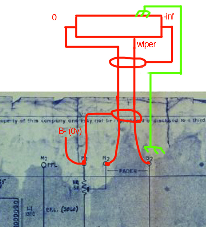
I've been doing an awful lot of wiring today, but I'm stumbling on how to wire the faders to the routing modules. This has been discussed in a couple of older threads but it's still a little unclear to me, so here is what i have so far, please correct me if anything's wrong:
pej0zpU.jpg

I'm am using classic Neve P&g 1520 faders. I understand there should be another cable going from the fader to B- (0v) for referencing. I kind of understand why that is, but can't really translate it into wiring. Can anybody tell me I should wire this? Also, there is a pair of switches inside the fader for fader kill and pfl. Does the fader kill one needs additional wiring or does it all happen in fader? What about the pfl ones, were they used in old neve boards?
Thank you, lads!
R.
 
The 5K trim pot (VR1) internal to the channel amp or router was not intended to have a connection to B-.  When used with a 1520 5K audio fader, it was there to adjust for small differences in gain between channels and was connected as an adjustable series resistance arm in the fader send. 
I don't have a drawing program on hand and can't find the original Neve wiring doc so, until someone comes up with a drawing, and from memory  :eek: 
First use a twin screened cable from the amplifier to the fader input and B-,  connect screen at the amp side only.  The conductors of this cable are are connected at the amp side to a B- point and the wiper of VR1.  At the fader side they connect to the fader input and bottom (0v).
Then use a single screened cable from the fader out to the amp's fader return.  Again, connect the screen only at one end, this time at the fader. 
In situ, there should be no need to make an earth connection between the amp and the fader as both will be screwed to the chassis.

I hope this helps a little, I'll try and draw something if no one else comes along
D.J.H.


Winston O'Boogie said:
The 5K trim pot (VR1) internal to the channel amp or router was not intended to have a connection to B-.  When used with a 1520 5K audio fader, it was there to adjust for small differences in gain between channels and was connected as an adjustable series resistance arm in the fader send. 
I don't have a drawing program on hand and can't find the original Neve wiring doc so, until someone comes up with a drawing, and from memory  :eek: 
First use a twin screened cable from the amplifier to the fader input and B-,  connect screen at the amp side only.  The conductors of this cable are are connected at the amp side to a B- point and the wiper of VR1.  At the fader side they connect to the fader input and bottom (0v).
Then use a single screened cable from the fader out to the amp's fader return.  Again, connect the screen only at one end, this time at the fader. 
In situ, there should be no need to make an earth connection between the amp and the fader as both will be screwed to the chassis.

I hope this helps a little, I'll try and draw something if no one else comes along
D.J.H.

Thanks! I knew about VR1 being a "fader trim"! The approach you're describing seems just fine, however I'm not sure that's how it was done in the old 8014 boards. I have many reference pictures and all show some weird daisy chaining between faders and only one double screened wire, as far as I can tell. 
xcbsAkg.jpg

f41pQuS.jpg

If only I had a neve console, I would have all my answers at hand..... wait....
 
The bottom picture doesn't look like original Neve wiring to me so, any one's guess there?
I suppose there can be several ways to wire up the faders.  On every old Neve desk I worked on, and on the one 8016 I owned for a short while, there were 2 distinct cables used for the audio signal to and from the faders. 
My desk did not have PFL wiring from the fader, just an absolute "kill" when the back switch engaged (not back "press") and then  "fader start" which had long since been disconnected.
 
Winston O'Boogie said:
The bottom picture doesn't look like original Neve wiring to me so, any one's guess there?
I suppose there can be several ways to wire up the faders.  On every old Neve desk I worked on, and on the one 8016 I owned for a short while, there were 2 distinct cables used for the audio signal to and from the faders. 
My desk did not have PFL wiring from the fader, just an absolute "kill" when the back switch engaged and then  "fader start" which had long since been disconnected.

Yes, the bottom picture is from API's 8014 rebuild thread here on gdiy. The new wiring was consistent with the old job, though. I don't care too much about pfl, though I guess fader kill is pretty much default on these boards..
 
OK well, on the drawing of how you have stuff wired, remove the connection at the amp to P2 (the bottom of the 5K trimmer) and just take that connection from the fader to a B- point on the amp.  Turn the trimmer so it's effectively out of the circuit.

 
remsouille said:
Ok, I'll sum it all up in total transparency so we can move on. The first picture I posted of the modules had Neve logos on them. Just to be clear, ALL THE ROUTING MODULES ON MY CONSOLE PROJECT DO HAVE NEVE LOGOS. When Ian first told me about a possible infringement, I photoshopped the logos out and reposted the photos

Ian is a great guy and you did the right thing in clearing things up and be honest, respect to Ian and respect to you.

remsouille said:
I was photoshopping the logos out out of courtesy for the trademark-sensitive folks out here and out of respect for the community.  I'll make sure I photoshop each and every photo from now on. Or maybe I shouldn't. Should I?

Reality is, you can do whatever you want, it's your build and your modules, no one has nothing to do with it.

But replying to your question, yes you should.
What you do privately it's your own business but this is a public forum and you should protect it.
 
Hi everybody,
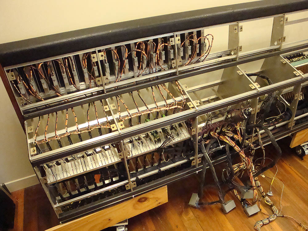
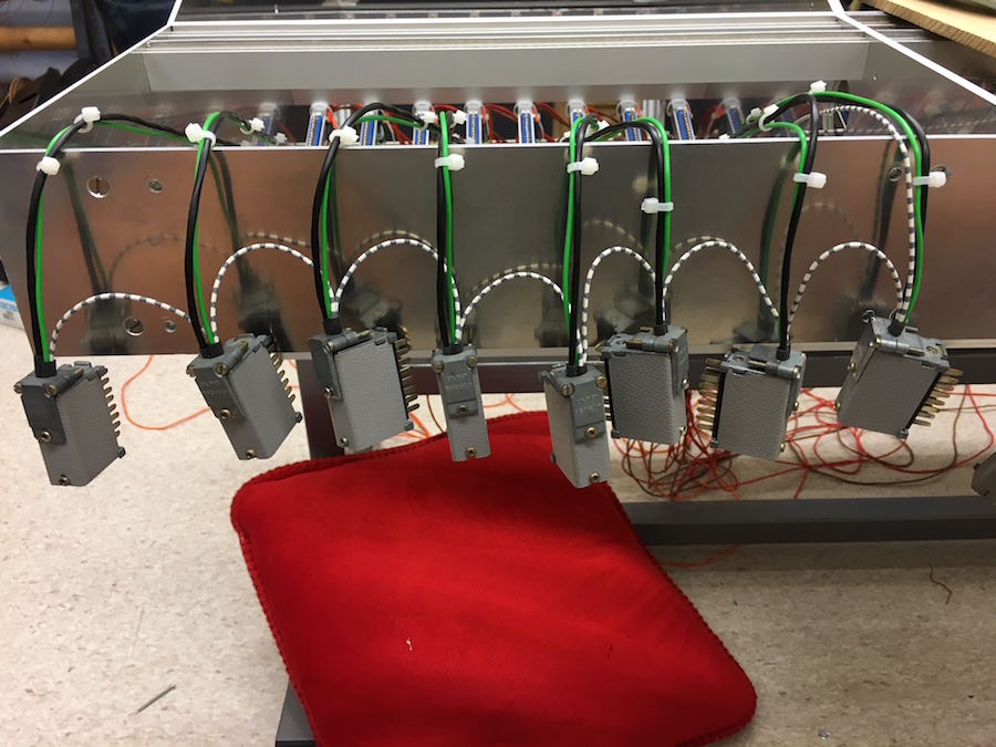
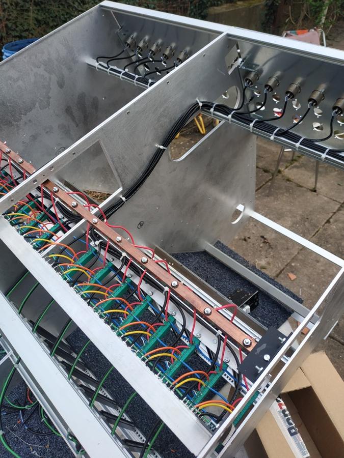
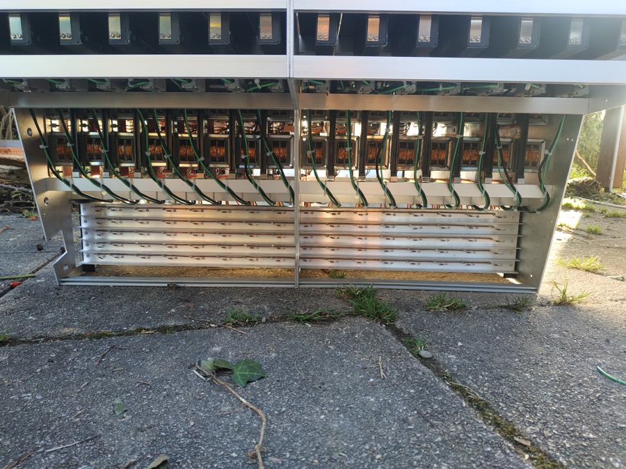
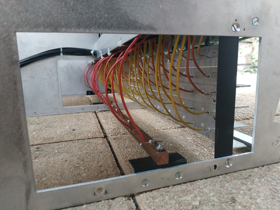
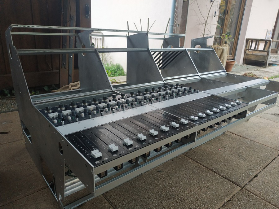
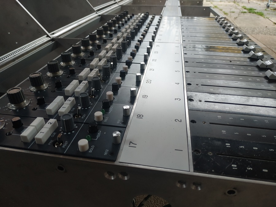
I hope everybody's alright in these strange times! Well, the good thing about that lockdown is that I get time to work on the console a lot. As a matter of fact, the right hand, tape return  side of the console is done( the mixing part at least, I still needsthe remote for the 16 track tape machine and the penthouse will house effects and stuff, more on that later  ;) ), and I've started assembling the left hand, recording side:
D5hY7cI.jpg

Y9kukEo.jpg

t1dE9db.jpg

OlRzM6q.jpg

sRDAZns.jpg

3A7oXea.jpg

Anyway, it still is an expensive pile of metal at the moment as I don't have 1272s nor a psu to test it. But at least, it looks pretty good  :).
I'm very bad at documenting the process, but I aknowledge the fact that this is something that probably hasn't been done before and wouldn't have been possible with the help of our great community, so I'll be happy to answer any questions regarding parts, design, etc...
Thank you all!

 
Goodness I love this picts!  Seeing that I'm at the point where I'm trying to find the best way to mount 500 series backplaces, these bus picts and edge connection picts have been very helpful.  If you have any other photos of progress, please, keep sharing!

Thanks for what you've provided thus far, and good luck on completing your project. Enormous undertaking!

Edit:  Just noticed the black, right angle plates used to suspend the copper bus bar.  Are they made of nylon or some such insulative material?
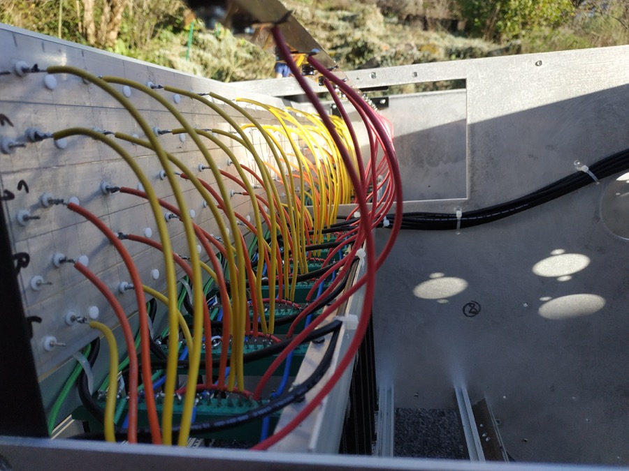
 
Thanks, man! It means a lot coming from you, with your insanely hardcore console project!!
The right angle plates are just PVC ones, that's the only suitable thing I could source locally. The original boards used blocks of something that's called paxolin, which is a sort wood mixed resin.... PVC will do ;)
I'll keep posting stuff for sure!
 
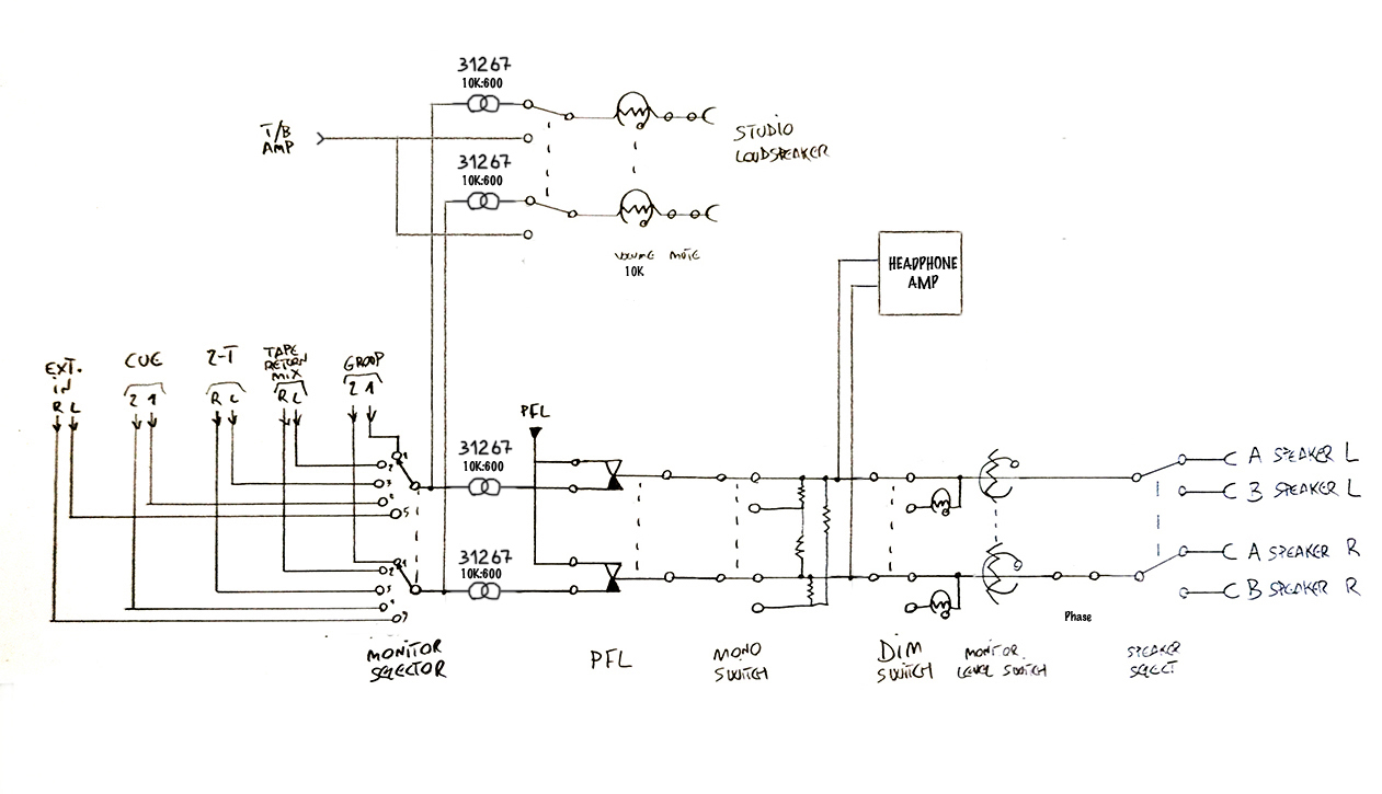
Hi guys! I've just drawn the block diagram for my monitoring section! If anyone sees something strange, please do tell!
The mono switch is probably the part that needs more thinking... I'd like to keep the whole thing passive, but if the mono switch absolutely requires an active element, what would it be?
ExxraT2.jpg
 
Hello

I'll probably put one more EXT in (you never know...) and AUX master send (if you don't have too much)
I guess you can monitor AUX return via channel PFL ? otherwise AUX ret can be useful to add too.

As for the output, one more change nothing in the design, and you'll blame yourself the day you add a third speaker paar, or anything you want to listen through.

For the studio section it could be nice to have a 3 way selector TB and CR input as it is, but also a independent input selection, that offer the ability to monitor/playback different input than control room.

An option (but which need relay) is to have your TB push button overwriting studio selector input to TB.

Best
Zam
 
zamproject said:
Hello

I'll probably put one more EXT in (you never know...) and AUX master send (if you don't have too much)
I guess you can monitor AUX return via channel PFL ? otherwise AUX ret can be useful to add too.
The EXT in will be accessible from the patchbay, so no need for an additional one!  Aux sends (2) and returns  (4) can all be monitored via channel PFL indeed, so no need to have them on the selector either. I hardly ever monitor the auxes anyway...
The reason Cue is on the selector is so that I can monitor the cue sends in stereo (the pfl channel is mono).

zamproject said:
As for the output, one more change nothing in the design, and you'll blame yourself the day you add a third speaker paar, or anything you want to listen through.
Ha! Well, I never use the second speaker output, so having a third would be a massive overkill haha

zamproject said:
For the studio section it could be nice to have a 3 way selector TB and CR input as it is, but also a independent input selection, that offer the ability to monitor/playback different input than control room.
I considered that ,but then again, though it doesn't show on the diagram, I intend to have the monitor input selector normalized to the studio input selector at the patchbay, so I can always have access to it there (though it would seldom happen.. I like the guys downstairs to hear the same thing I do so we're on the same page).

zamproject said:
An option (but which need relay) is to have your TB push button overwriting studio selector input to TB.
Again, that doesn't show on the diagram, but the "studio input selector" would indeed actually be the "talkback to studio switch". There will be 3  on-off-(on) talkback switches: talkback to cue, talkback to groups (slate) and talkback to studio speakers.

zamproject said:
C'est toi, le meilleur!
 
Hi Remsouille,

Cracking work man, looking real good !
Wished I had seen your post before today.

I've got a extrusion drawing for the  busbar , and have even gone down the road of getting quotes on a new die for extruding. 800 quid for the die, and a minimum order of 250KG....... :-\

I've got a build coming up,  basically rebuilding a vintage Neve console from ground up. Going to be a long old project, but I like to think of it as my 'Ferrari' in the garage  ;)
I've got all 24 routing modules, faders, monitor section, master section, some of the line amps, and 9 out of 10 of the side cheeks.

No Connectors...... Not enough rail and no 24x1060's  :eek: but thats another story !!

Ive also been in touch with Staffall (Sealectro) regarding the PTFE pressfit feedthroughs and the PTFE bushes.. not cheap AT ALL !!
011-1004-000-519  (tin lead plate white)
500 @$2.98 ea / 1000 @$1.87

011-1004-000-512 (tin lead plate red)
500@$3.87 ea / 1000 @$2.68

119-0014-000-009 (white)
500@$1.89 ea/ 1000@$1.26

119-0014-00-002 (red)
[email protected] ea / 1000@$2.27

:eek:

Did you manage to get  VERO to do a run of the single rail strip ? also, where did you get the 283 heatsinks from ? Ive got them drawn up in solidworks, but havent had them machined yet ?

Kudos to you brother  :)
 
Kid Squid said:
Hi Remsouille,

Cracking work man, looking real good !
Wished I had seen your post before today.
Thank you brother! Never too late!
Kid Squid said:
I've got a extrusion drawing for the  busbar , and have even gone down the road of getting quotes on a new die for extruding. 800 quid for the die, and a minimum order of 250KG....... :-\
Gee, that's a lot of extrusions!!!
Kid Squid said:
I've got a build coming up,  basically rebuilding a vintage Neve console from ground up. Going to be a long old project, but I like to think of it as my 'Ferrari' in the garage  ;)
I've got all 24 routing modules, faders, monitor section, master section, some of the line amps, and 9 out of 10 of the side cheeks.
WOOW! That's just great!! What routing modules do you have?
Kid Squid said:
No Connectors...... Not enough rail and no 24x1060's  :eek: but thats another story !!
Yeah, the amphenol connectors... I managed to find a batch of 250 a couple of years ago, fellow gdiy member API bought them all, maybe he might be willing to sell them, he's been away from Neve stuff for quite some time. Same thing for the heatsinks, he had them made, maybe he still have some, though they were not cheap!

Kid Squid said:
Ive also been in touch with Staffall (Sealectro) regarding the PTFE pressfit feedthroughs and the PTFE bushes.. not cheap AT ALL !!
011-1004-000-519  (tin lead plate white)
500 @$2.98 ea / 1000 @$1.87

011-1004-000-512 (tin lead plate red)
500@$3.87 ea / 1000 @$2.68

119-0014-000-009 (white)
500@$1.89 ea/ 1000@$1.26

119-0014-00-002 (red)
[email protected] ea / 1000@$2.27
This is just ridiculous hahaha I've been using the keystone stuff that you can find at Mouser, it's still expensive, but the last time I bought some, I picked smaller ones and they were cheaper, like 400@70cts each... Still a stupid price if you ask me. I talked to Blake Devitt about this issue, and unfortunately there doesn't seem to be a valid way around..
Kid Squid said:
Did you manage to get  VERO to do a run of the single rail strip ? also, where did you get the 283 heatsinks from ? Ive got them drawn up in solidworks, but havent had them machined yet ?
No, I just went very old school with a 1,5mm2 copper lead acting as the buss.. It means more ptfe pins, but I hear that vero strips have a way of failing sometimes.. And I like meself a nice chunk of copper :)
 
Hi Guys,
Quick question: Do you think it would be ok to feed 2 unbalanced busses from the  balanced output of a 1272, just taking the signal from the hot wire? Or would I have to un-balance the signal with a  transformer before hitting the busses?
I want my group's 1272s to have routing and insert functions, so I have it all in one unit. The path would have to be 1272 in > LO1166 out/insert send  > insert return > buss feeds/1272 out.  Adding a transformer for the buss feeds would really crowd up the modules, so if i can avoid it...
 
remsouille said:
Hi Guys,
Quick question: Do you think it would be ok to feed 2 unbalanced busses from the  balanced output of a 1272, just taking the signal from the hot wire?
Definitely not. The transformer is not only balanced it is floating so you would get no signal from just the hot  wire.
Or would I have to un-balance the signal with a  transformer before hitting the busses?
That would be the Neve way of doing it if you wanted routing AFTER the insert. If you want it BEFORE the insert then you can feed from the usual unbalanced output.
I want my group's 1272s to have routing and insert functions, so I have it all in one unit. The path would have to be 1272 in > LO1166 out/insert send  > insert return > buss feeds/1272 out.  Adding a transformer for the buss feeds would really crowd up the modules, so if i can avoid it...
There is only one 's' in bus and two in buses.

Cheers

Ian
[/quote]
 
ruffrecords said:
There is only one 's' in bus and two in buses.
HA! Thank you! That clears it all up! I almost thought bus and buss were different words altogether  :eek:
80hinhiding said:
Or as Ian suggested you can use the unbalanced output from the amp. 
That was my initial plan, then I realized it wouldn't make sense to have pre-insert feeds (to me at least). But it's alright, an extra input transformer will fit inside a 1272, it's just really tight but eh! What should I use, btw? Just a 31267 10K:600 ?
 

Latest posts

Back
Top