Official G7 microphone help thread

GroupDIY Audio Forum

Help Support GroupDIY Audio Forum:

This site may earn a commission from merchant affiliate links, including eBay, Amazon, and others.
My trafo is 125VAC, goes to about 185 after the bridge. 

10k dropping resistor gives 175V,    47k gives 120.   

for the 120 version with everything else stock I get 66V at the tube pin 6.  Center capsule is 58V at the voltage divider, pol 120/60. 

for the 175V version, polarization comes from splitting the H+ after the first cap:  85k dropping resistor gives about 130/65 V, while the internal microphone divider is changed by lowering ground resistor to 300K.   

These values need tweaking, 10-20k up or down if you want perfect voltages as it depends on the trafo etc.  Not easy unless one buys a whole set of resistors and nice ones get pricey.   
 
thanks for the fast reply!
But what exactly do you mean with  "splitting the H+ after the first cap"? Can you maybe mark on the schematic which resistor you changed to 85k?
 
It is an additional resistor that takes over the polarization, look at this schematic.  The values depend on your bridge voltage so it needs tweaking on your specific PSU.   

http://groupdiy.com/index.php?action=dlattach;topic=61399.0;attach=39145;image

An alternative is to make an additional divider inside the microphone, look here at the 100/300k on the polarization rail. Again it needs tweaking depending on your PSU.  Play with a voltage divider calculator after measuring what the PSU gives. 

http://groupdiy.com/index.php?action=dlattach;topic=51320.0;attach=17767;image
 
I think i am dead settled on this in-between config now:

-drop bridge voltage to 140V.    In my case I needed a 27K.    This ends up 75-77V at the tube pin 6 which is the same as in a U67, FWIW - I don't have a clue if it matters but it is the same tube after all....

-modify center-capsule divider by changing 470K with 390K to the ground.    I get about 60.5V.

-Insert additional divider on polarization rail inside mic:  replace 10K with 75K and add 430K to ground:  this gives about 120/60V polarization.   

These are existing resistor values I can get from Takman, nice Japanese metal film.  If you want to tweak some more I guess the best thing but more complicated is to use trimmers.

EDIT:  under load the PSU divider worked a bit funny, 142 HT was reduced to only 65V rather than 71 (no load it was 160/80).  So I reduced the first 100k to 75k and it is perfect, so far. 
 
I came back to my hometown and it took me an hour to spot the error.
It was microscopic short between output xformer pin and pattern supply pin.

I now have 146v on the supply with mic connected, without capsule

Tomorrow I'll mount the capsule and see if it works

Interesting thing is that I didn't need to play tricks with 10k resistor. Having 146v without any modification. And since I matched two 100k resistors, difference in pattern voltage is relatively good (0-75-146).
But I'll wait for definitive numbers until tube burns in and I attach capsule. This was measured 30sec after turning on the psu.

:)

Luka
 
After debugging a short on the pcb yesterday, today I've mounted the capsule an connected it to my test preamp.
IT WORKS!
Excellent!

It took some time for the sound to stabilize. In the first 5 minutes there was some popping and crackling, but when voltages settled it was all fine. Preliminary impression is that it sounds FANTASTIC! A bit dark, but in a nice way. Even though it's chinese capsule from the group buy (47 type), and I still have to put the right type of 1nF cap (still waiting for styroflex to be delivered, now it's supercheap box cap). I should also mention that my transformer is beyerdinamic 1:7

Voltages after 30 min of being plugged in are 147v and 73v - perfect!
All the patterns sound as they should.
And there's absolutely no hum, even when preamp gain is at max!

I'll post few pictures tomorrow!

:)

Luka
 
Jakob,  I tried the 11DQ10 diodes and it worked, heater increased from 5.6 to 6.05V  8)


Electronics can be pretty weird.  I received the PSU case and a bit of Gotham cable so I pretty much finished the thing (save for receiving a proper head, still using the improvised single layer one)

When I was done the hum increased noticeably.  But if I would touch the mic case it would reduce to the old level (when i had it connected through 3 xlr cables). Before it wasn't touch sensitive.  If I would put a bit of alu foil on the top of the grille (not completely closing it, just for the top)  it would be better.  Oh well, i thought " i'll wait for the denser grille".

Then I went on with checking voltages and managed to short the polarization (was set to card not 8 i think) and the heater with the dmm probe.  I thought nothing happened but after a minute or so noticed the tube was glowing.  Hmmm I thought, that's funny, never saw such a strong heater :))  (and it was a PF not EF).  Of course the regulator was shot, passing full 9V :D 
Ordered a new reg.  The tube is not dead but it has turned noisy (white/hiss not hum)    That's a pity because it was low noise before and much better than the EF I have (still humming badly with the new reg and higher voltage)

Now the strange part is that after replacing the regulator, the hum has decreased and the mic body is no longer touch sensitive!!


As a curiosity I tried my EF tube with 4.5V and surprise, no more hum at all.  So I guess the tube is fine, it is the regulator that makes the hum at 6V, probably because it still doesn't have enough input voltage to work well. 

The other surprise is the sound seems good. I didn't have time to do very careful tests but I don't hear any obvious degradation from the low heater.  Maybe just maybe there is a bit less gain (or is it low end?) 

 
I have experimented with underheating EF86.
I went all the way down to 5v and it actually sounded good!
As you lower the voltage you loose the low-mid, or shall I say upper bass. It starts to get less "tubey" and does sound a bit more cleaner, but it was too thin for my taste. Part of the sound of the tube mics (in my opinion) is that thickness in that lower range.
When I went back to 6v-6.3v I felt that was it!
YMMV

:)

L
 
I've found some mentions of this practice in older threads but it was more like theoretical/speculative talk, no reports of going so low. 

I spent a bit of time now with it comparing to a DPA 4011 which I consider "reference" and it still sounds a bit thicker than the SDC.  Anyway tomorrow I'll receive a few PF86s and go back to spec operation. 

I'd still want to fix the 6v option somehow, without changing the trafo.  It has two 6.3 windings, so perhaps I could add a simple CRC supply or if that is deemed noisy, add a low drop regulator.  Someone recommended me the LM2941

 
micaddict said:
The EF86 in Gefell tube mics is underheated, too.

Which has prolly been discussed here before, as well.

No, nothing here from what i can find with the search, only EC92 talk.  But thanks for the hint!  Learned that they kept using 5.8 after switching from EC92 to EF86. 

In my mic I found it is clean at 5.3V (added a 10k over the 1.8). I guess the hum would kick in at about 5.8 assuming the reg drops 2V and the Schottkys 1V. 
 
Gents,
So I broke my femur two inches below my hip.  The bottom half (my leg) rotated inside my leg and so I had to have 5 rods to put it back together and stabilize it.  Unfortunately I am somewhat immobile so can't get to the studio just yet and decided a Gyraf G7 build would help with my recovery.  Currently I have most of the components but I am struggling to find a good body.  There are some conflicting reports and was hoping someone could enlighten me as to what is tried and true.  I have exhausted the search engine.  I have no problem building the PSU.
You can also PM me.

Will the G7 pcb fit into an Apex 460 if trimmed a good deal?
Some claim to have done it but when asked about it they never replied.

Is the Auracyle ht-11a body the same body as the apex 460?

Will the MXL V69 work as a donor body?

Now although its ugly, the Behringer T-47 dimensions are 215mm (8.46'') in length with a max diameter of 62mm (2.44'').  The T-47 does taper and I can't find what the diameter is at the mic narrowest point but just eyeballing it, the body looks promising.  The T-1 is a bit wider with a 68mm (2.68'') diameter at its max  and equally as long.   
Anyone?

I have read of people using two donor mics with one on top of the other.  Has anyone done this and what mic did they use?

And finally;  what bodies are there to use.


Hey  Rocinnate,

I wish you a fast recovery!
Sounds very painful...

Did you think about building a body? That for sure could help recovery ;)

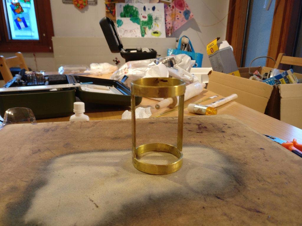
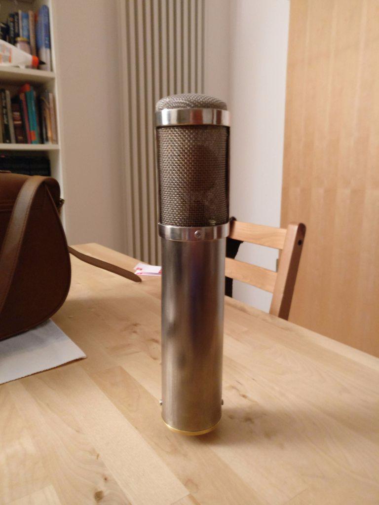
I did one from a piece of brass pipe with a bar rail end cap, after Isaw that some other people did their own body too.
From my point of view it gives the DIY a whole new dimension
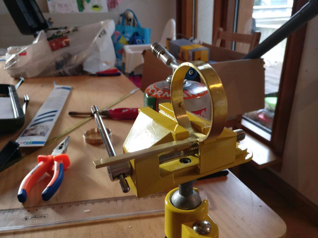
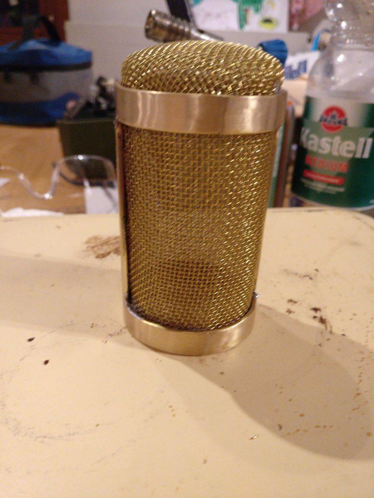
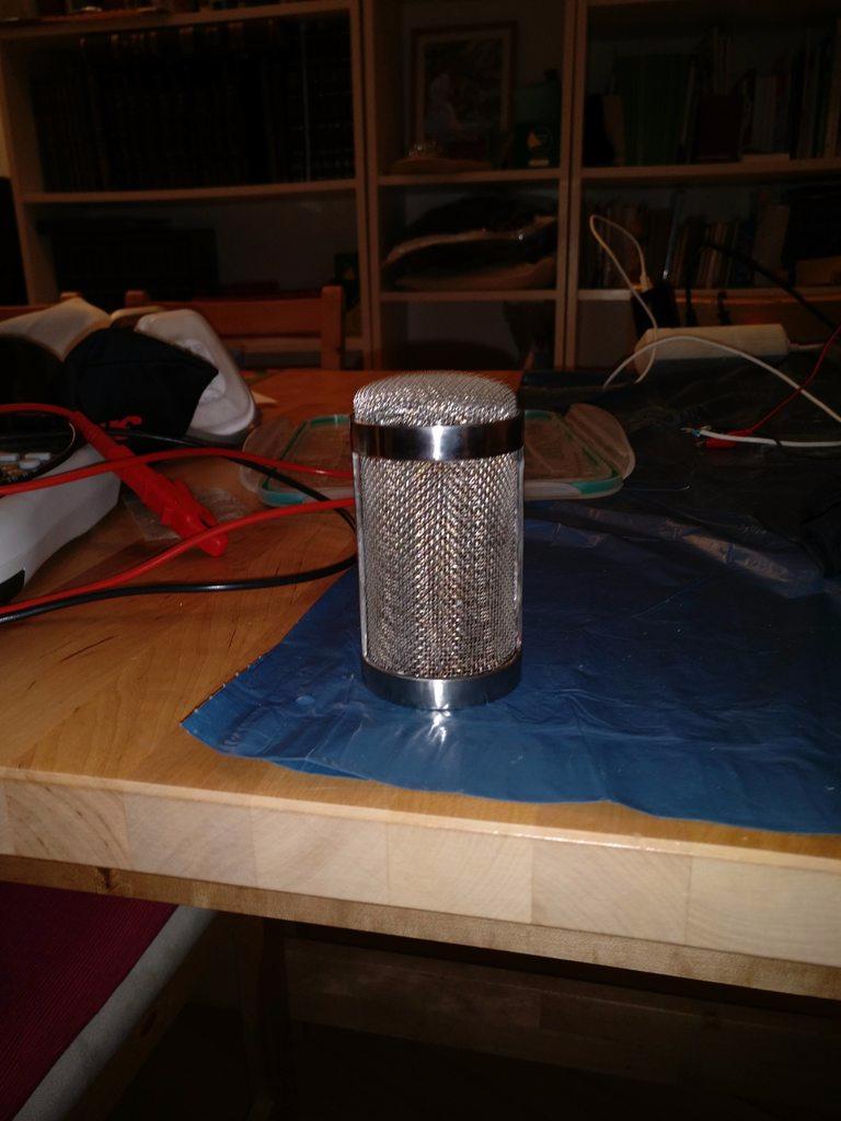
I now got to the point where I finished a headbasket, I'm not 100% satisfied with it though.

m2tzLJl.jpg

Silver soldering the headbasket, my first time hard soldering.

CkyQEnM.jpg

...let me tell you, that stuff is nasty...

HzRAG3i.jpg

Did a double layer mesh , but I don't like the high frequency response after all.
Got a Beesneez CK12 in there.
So now I'm thinking about doing a M49 or U67 shaped headbasket with one layer of coarse mesh.

5tEb5wp.jpg

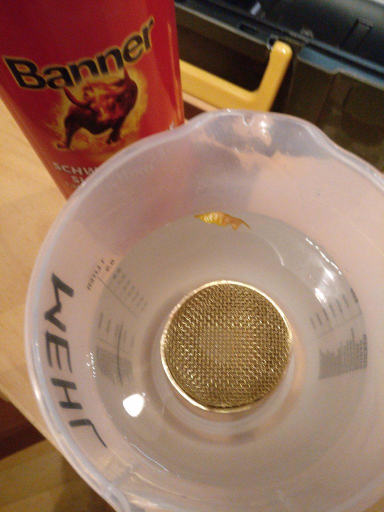
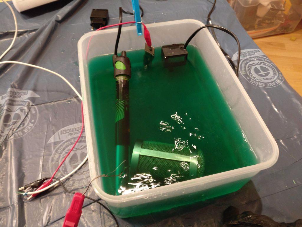
Pickling the headbasket in sulfuric acid (really nasty too).
Two mistakes I made, one I didn't sufficiently clean the piece from oils and remainders of the (very nasty) solder paste.
Second, the sulfuric acid I used was pretty weak, only 25%. I think I need higher percentage...

E9rEPgW.jpg

And the final plating process. (Dig the green stuff? yikes)

g1yabRP.jpg

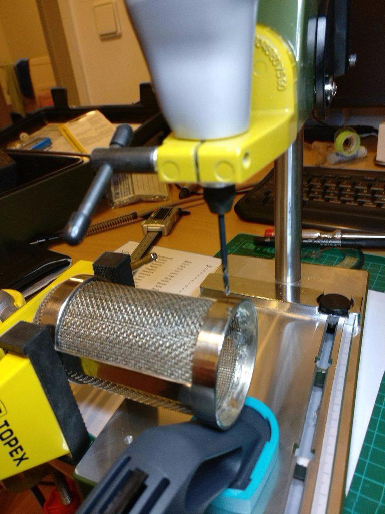
do not drill after plating ::)
gEVsZN9.jpg

HKlCg6c.jpg


It's not the easy road, but where is the fun in that? ;D
What's for sure, the more I DIY, the more I learn...
 
It's awesome.  The head-basket looks a bit involved for me right now but definitely doable.  Where did you get the brass bar? Inner diameter of 2 inches if I recall correctly.  And I would guess 200mm in length should be fine.  Is there a thickness i should look at?  I also have no way to cut it right now as I'm kinda unable to get to my shop but  I can search online. Thanks.
 
Hey thanks.

Actually the brass bar was the easiest part, as I got it from the local hardware store.
I used 10x2mm brass bar, but that's a bit overkill, next time I would use 1mm thickness.

The inner diameter is 50mm, but that really depends on what you want. the brass tubes are available at various diameters.
Regarding thickness of the tube wall I would stay in the 1mm range too.

You could also try to find a piece of piepe that fits exactly over the diameter of the body sleeve and then cut out the windows for the mesh.
 

Latest posts

Back
Top