official GDIY51PSU Help & Support Thread

GroupDIY Audio Forum

Help Support GroupDIY Audio Forum:

This site may earn a commission from merchant affiliate links, including eBay, Amazon, and others.
A question about this design-

I have a psu requirement of +/- 32 and +/- 28 for a project on my bench. As designed, can I put a 120:32+32 like http://www.antekinc.com/details.php?p=665 in front of this to get my voltages? LM350 can rock 33v... Im looking at running ~40 DOAs, so maybe I should bump to the 200VA. The 32v rails do not have such a load, but 28v...

This would be a great solution over the $500 commercial version that probably cant juice the whole thing. 

Thanks for any input-
 
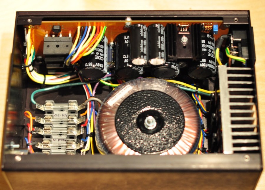
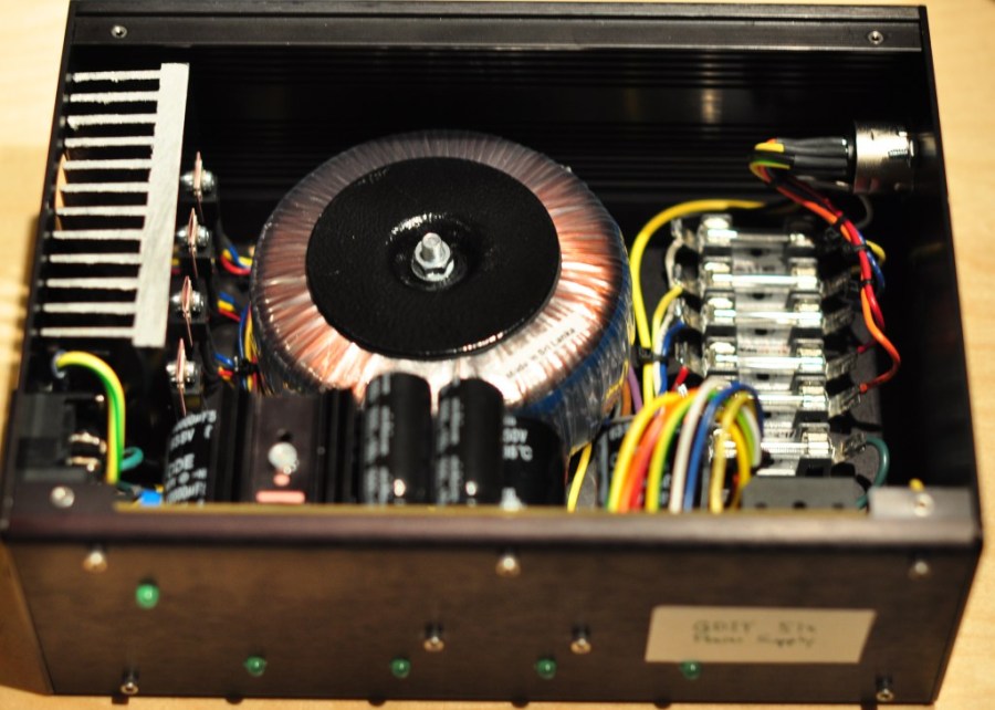
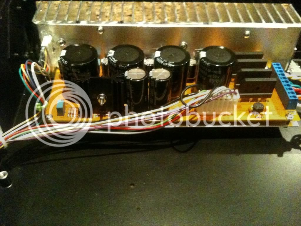
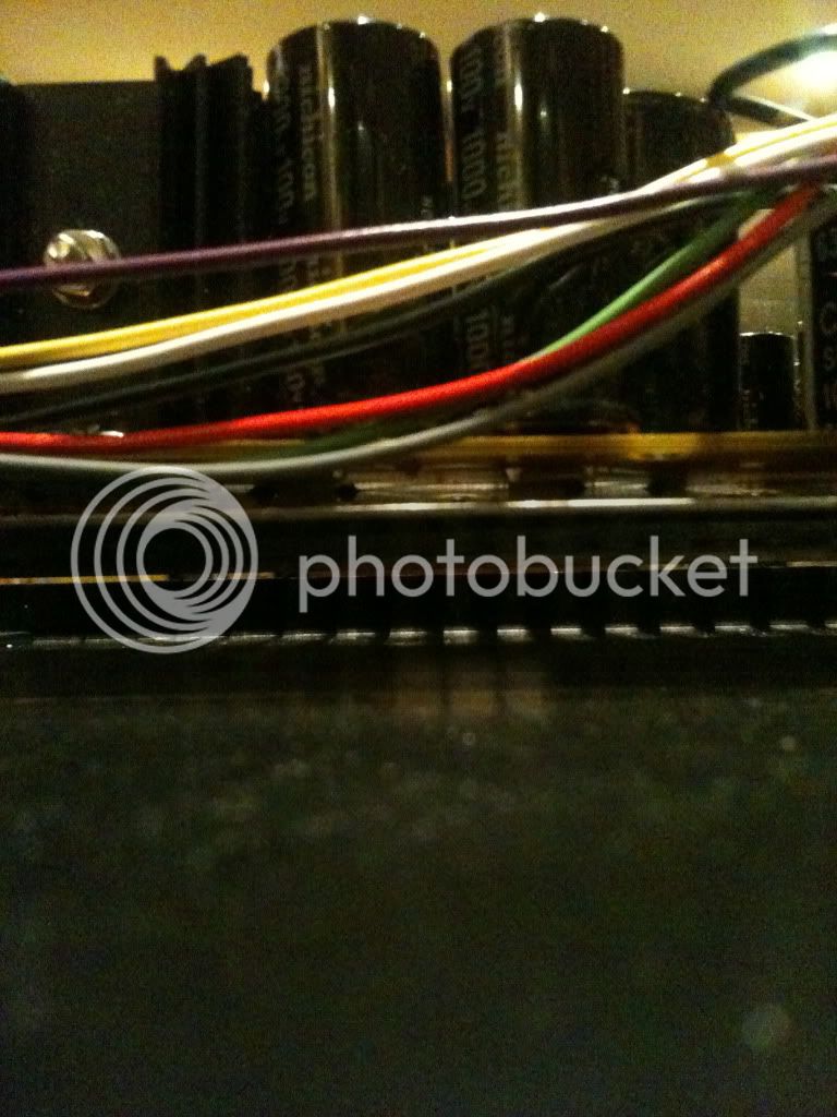
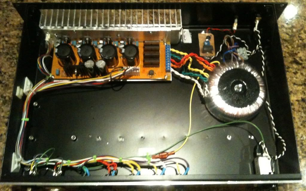
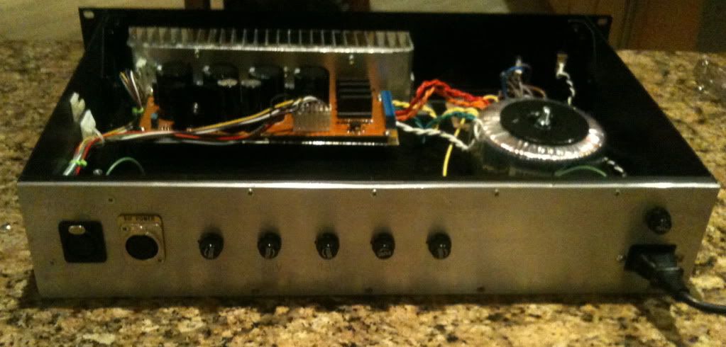
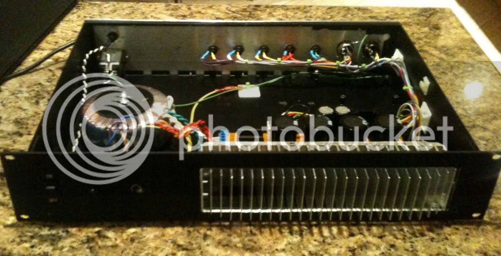
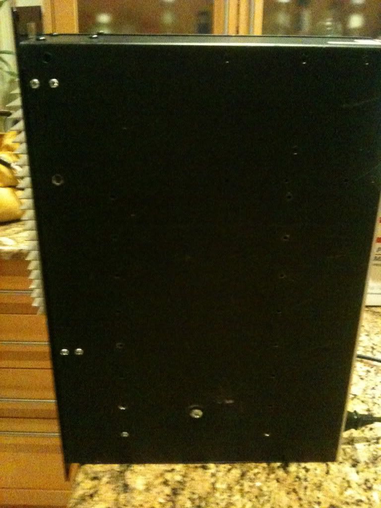
I just finished my 51x power supply, and wanted to share a couple pics so perhaps some people could get some ideas.  I repurposed a case from a previous project that is just barely large enough, but the final result seems to work great.  I have no expectations that this form factor will power 11 full modules without getting too hot, but here it is nonetheless:

psu1.jpg

psu2.jpg
 
rack build question
Am i missing something ?
the back of the end pieces for my 51 rack don't seem to line up ?
this is the back panel in relation ship to the side pieces
I can't get the screws to fit into both parts , actually not past
the back plate
it seems solid enough without them , but not sure
if i've done anything wrong or the fit just is not good
pedalwood024.jpg

pedalwood026.jpg

pedalwood025.jpg
 
All parts are CNC cut therefore the fit would normally be good.

However, some modules may have heavier and irregular paint build up around the holes. I would suggest to scrape the paint off the holes.
 
did you try loosening all the screws that ARE in a bit and trying to line things up after that.  I dont think i've ever gotten a case to fit together without problems on the first go.
 
I tried [ several times ] with all the screws 1/2 way in ,
but there doesn't seem to be much wiggle room ,
either one part lines and the another doesn't
I'm not even sure i could strip them in .
 
I am totally certain that it is caused by paint build up. Perhaps you should remove the back panel and scrape the paint in all of the holes.

However, we had two occassions where the side panels had the screw holes misaligned. I have no idea how could that be the case but they were. This week I will meet up with the metal fabricator to investigate how they got into the batch. If you do not mind holding on a bit, I will send spares to Jeff with the next run and he can send you a new back panel.
 
Hi Greg,

Just cheked it on few panels that I have in hand and I can confirm that indeed it is caused by the paint build up. I have put a small screw driver through all the holes to clear the paint and the panel fits perfectly.

Kind regards,

Cemal
 
concerning the power connectors: bad idea to use a Sub D ?
Pins are at least the size or bigger than the Neutrik ones. Solves the space issue as well IMO
 
Hello,

I have a little problem with my psu. I keep blowing fuses. Even with the sec. side of the transformer not connected to the pcb. I connected a white wire to a yellow wire on the prim. side of the transformer like this yellow-white/yellow-white. I used a 1A fuse.

What do i wrong?

Thanks,
Pieter
 
Well, it took me a year and a half to do it but I finally finished (sorry for the crappy iPhone pics):

photo2yr.jpg


photo1wp.jpg


The only thing I need to do now is dress (cable-tie) the wiring and relocate the power tranny (it was too close to the switch).

Thanks to all! Truly!

Chris
 
I did a second supply using the DIY 51X PSU card, using what I learned on the first one.  Thought I would put up some pictures.  It is improved from my last effort, from what I learned doing that one.

This time, I mounted the PSU card to an L shaped aluminum plate, and screwed that to the heat sink, with heat sink compound.  That way, I can get at the screws on the regulators and still use the nice mounting placement (along the edge) that Silent Arts did.

Also, because the 48 V regulator is at the back of the card, I floated the whole card and mounting plate about 1/2 inch above the bottom of the case, and mounted it to the heat sink.  Then I left the heat sink well inside the case, so that there is a lot of airflow.

At this point, air can circulate completely around the PSU card, with a huge opening, and very little restriction.  The heat on the main regulators should actually increase that circulation for the 48V regulator, with no fan.  I can't wait to load it down and see how it does.

There are 2 outputs, in DIY-51x 7pin XLR format and API-500 5pin XLR format.  Each LED is lit after the fuse (unlike my first attempt, which I need to rewire) so I can tell what happened if I lose a rail because a fuse blows.

The mains light is an LED with some old high voltage caps and a regulator I had lying around based upon t http://www.marcspages.co.uk/tech/6103.htm, which is the way I did it last time too.

I have enough power now, but if these boards ever get made again, it could be really easy if they had:
1) fuses on board, before the LED mount points.
2) Regulators all on one edge, and lined up so you could get a screwdriver on the heatsink without hitting a big cap.

If that was the case, these would be a breeze to assemble, and cool.  They would have to be a bit longer of course, but they would still fit fine in a 19" rack.

(Mr Arts et. al. please take no offense, these are beautiful cards and a really nice project, thanks so much for doing them.)

Case is re-used, and the LED's, heatsink, 1 xlr, mounting brackets, and various components.

Like last time, with this great board, it all worked the first time I turned it on, just a little trimming of voltages.  I still need to get a few of flat head 6/32 screws for bottom of the case, so it won't scratch the adjacent component, but it is all up and working.

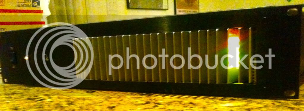
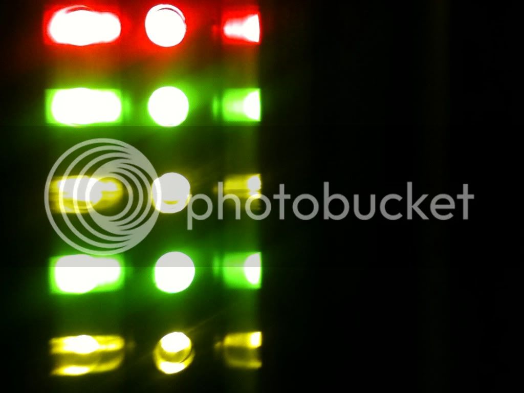
Front looks slick, lights indicate +48,+24,-24,+16,-16 in that order, top to bottom.

IMG_0670.jpg


Close up between the fins.

IMG_0671.jpg


Board mounts to an L shaped aluminum plate, which bolts to the heat sink with compound between.  Floats above the case floor for circulation.

IMG_0664.jpg


Here is a shot, with my iphone, under the board so you can see the vent area.  You are looking at the back of the face plate, but there is almost 2 inches of space between that and the back of the fins, and so you can blow a gale through there really easy, top and bottom.

IMG_0665.jpg


Case is layed out better than my last one, because I built a new front and back panel, so I could orient them correctly to keep the Toroid away from everything else (distance is nature's mu-metal).

IMG_0660.jpg


IMG_0661.jpg


IMG_0662.jpg


IMG_0672.jpg


IMG_0676.jpg
 
Thanks so much for your kind comments....

I love it when something that works well, can look good too.  They go together in most things.

I have a related question for you.

I notice the quality of your PCB's is superb! I have 2 of your PSU's, 2 GroupDIY rack PCB's and a couple of the prototyping card edges I got through ClassicApi...  All of them are excellent.

What I want to know is, how can I have PCB's made with a similar level of quality?
Beyond the Gerber files, and design, which of course I must provide..
Is the key to your quality level materials? Copper weight? Coatings? or just choosing the right manufacturer?
What specifications must I provide in order to approach the quality level you achieve?

I like the glossy coating, the gold (plating, or flash)? the solidity of the substrate material, the cleanlyness of the cuts (edges) and the clarity and beauty of the notation, I even like the colors you chose.

If there is a proprietary or secret aspect to this, apologies in advance.  but any help you could provide I would greatly appreciate.  Your PCB's are the best I have seen, bar none.

Note that I am in the USA, and so if you know of a good manufacturer, please take that into account.

Best regards
 

Latest posts

Back
Top