official GDIY51PSU Help & Support Thread

GroupDIY Audio Forum

Help Support GroupDIY Audio Forum:

This site may earn a commission from merchant affiliate links, including eBay, Amazon, and others.
bruce0 said:
...
If there is a proprietary or secret aspect to this, apologies in advance.  but any help you could provide I would greatly appreciate.  Your PCB's are the best I have seen, bar none.

cool, thanks :) nice you like the PCBs ;D
there are no secrets, the manufacture is www.pcbcart.com in china.
(like many of us use)

bruce0 said:
What I want to know is, how can I have PCB's made with a similar level of quality?
besides of a good manufacture it is a mixture of everything in your Gerber Files, I guess.
"clarity and beauty of the notation" - I don't use the standard library my software offers, I did my own. I must have been lucky choosing the right font / font-size / line-thickness / pad diameter. doing the library your own, it doesn't look like all the other silkscreens ;)
"the cleanlyness of the cuts (edges)" - well, the backplane and the PSU are just rectangular. for the card edges, make sure your each line / circle ends exactly where the next line starts
"and design" - important part ;)  I always want my PCBs looking good. stupid, since once they are build in an enclosure you don't see them anymore. however, it takes a much longer time, but I have more fun designing them like this (3D rendering is a big improvement for this part), and you to stuff them.

all the rest is part of the manufacture, I can't even tell you if I have plating or flash gold fingers.

hope this helps,
if you have further questions please shoot me a pm.
 
Hey sws, that's a great build I love the tightness and layout. I think I will do something similar if I can find an appropriate box, maybe an old tin breadbox or something. I love the official racks but I love more putting my own together that is more space efficient. I wonder if you could get more modules powered with your setup just by routing more cooling holes in the case or would you need a bigger heatsink. I'm going with the official heatsink from Jeff. Thanks for sharing your build!


sws said:
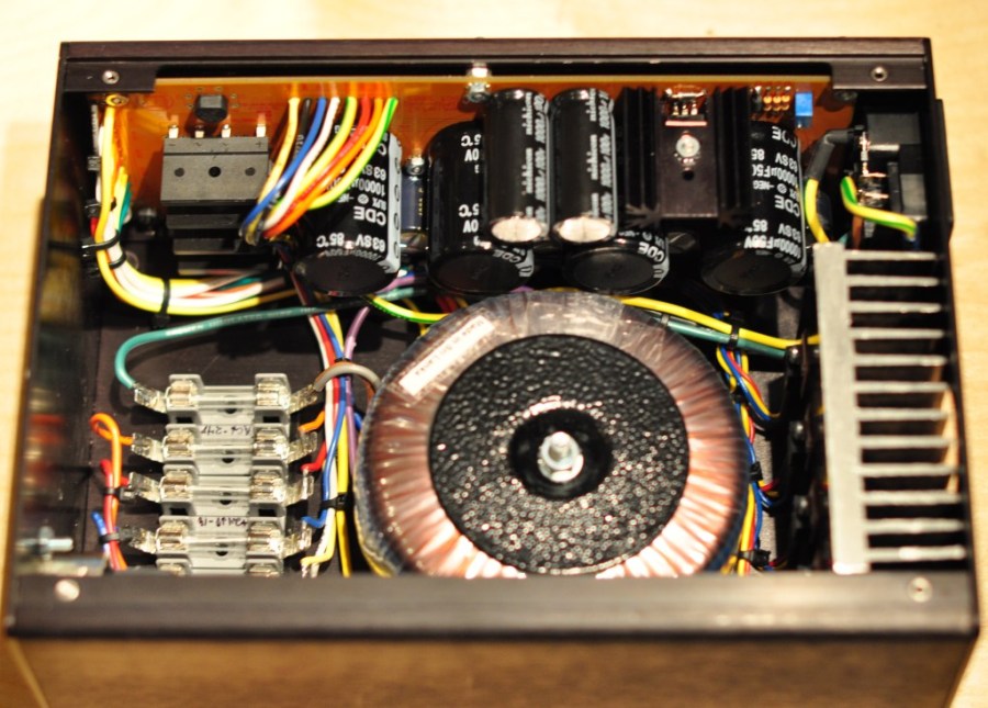
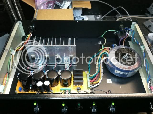
I just finished my 51x power supply, and wanted to share a couple pics so perhaps some people could get some ideas.  I repurposed a case from a previous project that is just barely large enough, but the final result seems to work great.  I have no expectations that this form factor will power 11 full modules without getting too hot, but here it is nonetheless:

psu1.jpg
 
Hey all, what are the insulating washers that you use between the mounting screwhead and tab of the regulators? I'm not even sure what terms to search for at digikey.
 
does anyone have a pdf or something similar that can be used as a drill template for the metal work for the psu pcb? i jumped the gun and soldered all the components on when the board came in and i didn't think about waiting till i had my metal work ready.... if some body could just scan the top side unpopulated board and make it a pdf that would be awesome. i'm gonna start doing this with every project i get so i don't do this again

dk
 
guys,

quick NOOB wiring question: I'm re-using a 2u case that I have here for my PSU, and it already has an IEC connector on board with separate fuse.
Since I won't be using the 240/120v switch (I'm only running 120v), I don't want to screw up the power connections.

I'm using Jeff's power trafo, do I need to connect both sets of 115v leads or am I just using one pair? Brown + Purple for instance, and leave Grey + Blue disconnected?

thanks, I'm trying not blow anything up, or electrocute myself.  :D
 
You can use only one 120V primary (Brown / Purple) and tape up the other (Grey / Blue).

Or you can parallel both primaries (Brown + Grey / Purple + Blue).

On above I am assuming that;

Brown: 0V
Purple: 120V

Grey: 0V
Blue: 120V

 
It's actually the other way around:
Brown= 115v
Purple= 0v

Grey= 115v
Blue= 0v

But, yeah, thanks, that's what I needed. So you're saying I can just solder each 115v together and each 0v together? Is there any difference/advantage to that as opposed to just taping off the uneeded ones?

Either way, is this how I would wire it:
(from Jeff's post-)
All of these references are from a viewpoint if you are inside the case looking at the inside of case side of each part.

IEC
-Top Lug of IEC --> Chassis star ground stud- GROUND
-Right Lug of IEC --> Fuse Holder Side Lug- 115v
-Left Lug of IEC --> Top Right Lug on front panel main switch- 0v

???

Thanks Sahib!
 
You are welcome.

No advantages no disadvantages either. But I would parallel them for not to go waste.

Jeff's IEC connection is correct. If you  look at the IEC either from the inside or outside L, N, E are actually marked as Live, Neutral and Earth. You can't go wrong.
 
SUCCESS!!!

It's not as pretty as Sahib's, or many of you, but it was very cost effective, and most importantly, it works!

I "re-appropriated" a 2u chassis, and got the heatsink off eBay for $7. One of my inline fuse holders came without it's cap, luckily I can do without it until a replacement comes, because I don't have any 24v modules (yet :) ). But I have tested all voltages in the 51x rack and everything is solid.
I am losing .1v on the 48v in between the PSU and rack, but that shouldn't really be a problem, eh?

385134_10150366754241991_526456990_8655215_1353399864_n.jpg


Thanks to Volker, Sahib, Jeff and Chunger!!! Couldn't have done this without you guys!

cheers all
Eric
 
Hi guys,

My very first post here even if i've been lurking around for the last few months. Recently purchased a kit from volker, which i've just completed and everything powered up well on the first attempt. I custom racked the PSU as I wanted it to be smaller than the official one (still not as small as i would have wanted it to be though, but i haven't been able to do better). All the voltage rails are behaving well and all the diodes light as expected.
By the way, i do remember about a post from Jeff explaining he set all the rails a bit higher than 16/24V but i can't find it anymore and i don't remeber the values he advised. Does someone remember?


I'm already running a pair of VP312 and waiting for my mouser cart to complete a pair of NV73. Also can't wait to purchase david's 1176 and peter's 525 and LA3A.

Anyway I wanted to say many thanks to everyone involved in this project, especially Volker, Jeff and David. Also special thank you to Chunger as your "newbie" thread has been HUGE help. This build has been real fun and even though i didn't save a lot of money compared to a regular lunchbox, i now feel way more comfortable with its architecture, and now benefit from the 24V rails wich is a real plus.

Thanks again

François
 
I go about 1V or so high to make up for the voltage drop over the protection diodes found on each module. So 17V and 25V. I keep the 48V set pretty accurate as most cards don't use a diode for that pin.
 
Thanks for you fast reply Jeff.

Do you set these voltage with the PSU connected to some modules or running alone?

Best regards

François
 
I believe Cemal just posted somewhere that he saw a sag of 100mV or so from unloaded to under full load. That said, it shouldn't much matter. You could always set it unloaded and then see where it's at after you fill the rack up and start putting the modules themselves under load. For example, a VP26 driving a 600ohm load will draw more current than if it's sitting idle.
 
Call for help :

Somehow in the process of moving house, the 511 front panel which I carefully packed (obviously not carefully enough!) has been both scratched and warped.  Not only does it now look pretty bad, but it won't even fit the rest of the metalwork because it bends outwards.  I may be able to solve this warping with some careful bending back, but the scratches are unrepairable.  I am absolutely gutted  :'( :'( :'(

Do any of the worldwide 51x dealers have PSU front panel spares? 
 
Back
Top