You are using an out of date browser. It may not display this or other websites correctly.
You should upgrade or use an alternative browser.
You should upgrade or use an alternative browser.
official GDIY51PSU Help & Support Thread
- Thread starter [silent:arts]
- Start date


Help Support GroupDIY Audio Forum:
This site may earn a commission from merchant affiliate
links, including eBay, Amazon, and others.

Thanks for the pics! Looks very nice! Great work! ")
Hi all,
I have a couple of questions to ask (too many pages for search ;D)
-What the value of the main fuse ? i'm in France main voltage 220V
I see in chunger thread 1.6 amp for + - 16v, and + - 24v. 125mAh for 48v. so 6,525 Amp max
But in Volker transfo it's print 188VA
For me P=UxI so 188 = 220 x I
I = 85mA ???
I'm lost !
-I buy wire to ptowkid but it's 24 AWG :-\ (re :-\ and no informations on website)
if i see here http://www.powerstream.com/Wire_Size.htm i need 20Awg ?
Is it good or i can solder this 24 wire
Thx a lot gentlemen 8)
I have a couple of questions to ask (too many pages for search ;D)
-What the value of the main fuse ? i'm in France main voltage 220V
I see in chunger thread 1.6 amp for + - 16v, and + - 24v. 125mAh for 48v. so 6,525 Amp max
But in Volker transfo it's print 188VA
For me P=UxI so 188 = 220 x I
I = 85mA ???
I'm lost !
-I buy wire to ptowkid but it's 24 AWG :-\ (re :-\ and
no informations on website)if i see here http://www.powerstream.com/Wire_Size.htm i need 20Awg ?
Is it good or i can solder this 24 wire
Thx a lot gentlemen 8)
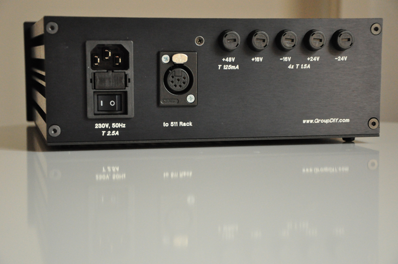
Main fuse: T5AL250V
+16V/-16V and +24V/-24V rails: 2A
+48V: 100mA
This was supplied to me in the electrical wiring kit that came with the PSU case from Mr Cemal. I live in Sweden (240V).
I did a search and what I came up with is this quote from one of Mr Cemal' s posts:
"between 0.7mm (21AWG) and 1mm (18AWG) of ordinary copper wire should be fine."
I hope I could be of any help for the first time on this great forum.
Kind regards
Magnus
sahib
Well-known member
Magnus is correct.
No offence to ptown but 24awg is extremely thin.
No offence to ptown but 24awg is extremely thin.


$15.98
$16.98
Gikfun Upgraded USB Mini Amplifier Electronic Transparent Stereo Speaker Box Sound Amplifier DIY Kit for Arduino EK1918
Gikfun_Official_Store
![Soldering Iron Kit, 120W LED Digital Advanced Solder Iron Soldering Gun kit, 110V Welding Tools, Smart Temperature Control [356℉-932℉], Extra 5pcs Tips, Auto Sleep, Temp Calibration, Orange](https://m.media-amazon.com/images/I/51sFKu9SdeL._SL500_.jpg)


Axelerator
Well-known member
hi everybody &
have a nice eastern also !
-just finishing the final cabeling of cemals dual power supply (btw. the most satisfying diy so far due to really nice prework ! )
still confused about grounding even after seeing all the photos here, with ground from psu board going to the fuse board ( as suggested ) and then to
the ground of the neutrik (?)
-where it hits the star ground via physical chassis connection of the neutriks ?
and one wire from psu chassis to star ground means that the 511x rack chassis is routed via psu board to the star ground ?
please , somebody explain it to me :
i would have thought other way round ?..
greets and congrats everybody to their finished projects !
axel
Brolik
Well-known member
When you say 'Dual Power Supply', do you mean that you have the new rack mount psu design that Cemal was working on? If so, where do I get one, huh? I'm out of space in my 51x bucket, and need to expand. What's up wif my sweet new psu solution, eh?
sahib
Well-known member
Brolik,
I have four left. Please e-mail me at [email protected]
Axel,
There are two grounds.
First one is the circuit or analogue ground. This is the ground that the regulator circuitry has as the reference for the rail voltages.
The second one is the chassis/safety ground that comes from the mains. This is the middle tab on the IEC.
The analogue ground comes out of the regulator board and goes into the fuse board. Comes out of the fuse board and goes to the 7 pin Neutrik.
The reason for that is that we need a ground for the status LEDs to function.
On the 511 rack the ground connections are jumper selectable. This is good because there are times that you may need to lift the module off the chassis ground due to hum. So I suggest you leave it selectable on the 511 rack.
However, you must tie the analogue ground to the chassis ground at the chassis star point inside the psu case.
On the output terminals of the regulator board there is a chassis ground connection. Connect it to the star point. Also on the regulator PCB there is a header/jumper immediately next to the input terminals which allows you to connect the analogue ground to chassis.. You can solder jumper it. Check to make sure both are joined and you are done.
Axelerator
Well-known member
Ok cemal thx for clearing up
i know there are two grounds but on the photos of the ready units above i could not see the front jumper cabeled so i thought i was
missing something here !
now i can finish the last connections and fire up !
greets as always
axel
i know there are two grounds but on the photos of the ready units above i could not see the front jumper cabeled so i thought i was
missing something here !
now i can finish the last connections and fire up !
greets as always
axel
sahib
Well-known member
Hey Axel,
Did not mean to patronise. Just wanted to clarify. Glad to hear all coming along well.
Kind regards,
Cemal
Did not mean to patronise. Just wanted to clarify. Glad to hear all coming along well.
Kind regards,
Cemal
Thx for your feedbacksahib said:Magnus is correct.
No offence to ptown but 24awg is extremely thin.
Axelerator
Well-known member
yeah just fired up like a charmhappy ajusting voltages just now
big thanks and i certanly did not felt patronised
just nicest thing on this forum is people are willing to explain again..and again 8)
cheers
axel
Denyle Guitars
Well-known member
Also, how do you connect the sinks to the power supply boards, can you show us pictures of the guts?


[silent:arts]
Well-known member
Denyle Guitars:
8) 8) 8)
very very nice !!!
8) 8) 8)
very very nice !!!
Nicely done. Beautiful. So the Heatsinks are the sides of the cabinet. It is hard to get those darn screws in there between the caps and the heatsinks I am sure ( i kept getting shorts because the shoulder insulators were out of alignment.
Thanks for the guts shot. A really nice build.
Thanks for the guts shot. A really nice build.
sahib
Well-known member
I am very impressed indeed by how Denyle got those screws but if you can align the holes between the fins then you can always screw the regulators from the outside by having the nuts/washers inside. Alternatively if you have access to a milling machine you can shave the fins and again screw from the outside.
The other side is fins... which makes it hard to put screws in there... and invariably the spacing of the fins does not match the spacing of the regulators on the card.... (And in my case there was an aesthetic issue too... as my heatsink was the front panel..... and I didn't want to mess up the look of the fins). In my second one, I mounted the heatsinks aluminum sheet screws from behind, and then as you say milled (i just drilled shallow holes) for the screw heads in the back of the heat sink, and then mounted the plate to the heat sink... with compound between... All the while thinking there has to be a better way.
"One wishes" that it were possible to arrange the board so that the regulators line up with the spaces between the caps. Which would make it all a piece of cake.
Denyl's build is as clean as can be... even with the difficulties.... really great
"One wishes" that it were possible to arrange the board so that the regulators line up with the spaces between the caps. Which would make it all a piece of cake.
Denyl's build is as clean as can be... even with the difficulties.... really great
culteousness1
Well-known member
Finished this a while ago...
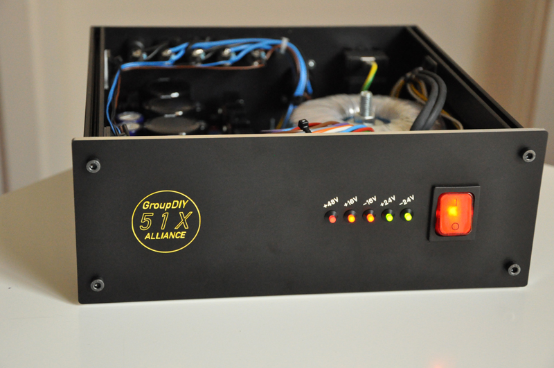
Everything went smooth. Thanks to the whole 51x-Crew and Frank at NRG for the engravings!
Cheers,
Carsten
Everything went smooth. Thanks to the whole 51x-Crew and Frank at NRG for the engravings!
Cheers,
Carsten
sahib
Well-known member
Great build. Excellent stuff.
Similar threads
- Replies
- 228
- Views
- 76K
Latest posts
-
-
AKG Perception P220 to Neumann u87 5 min mod ( p200, p100, p400, p420? )
- Latest: Masiusima13
-

-
-

-
-