Small 4ch mixing console build

GroupDIY Audio Forum

Help Support GroupDIY Audio Forum:

This site may earn a commission from merchant affiliate links, including eBay, Amazon, and others.

efinque

Well-known member
Joined
Jan 3, 2018
Messages
376
Sup GDIY,

after building DJ mixers I decided it's time for a small format live/studio mixing console.

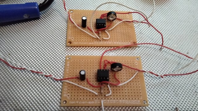
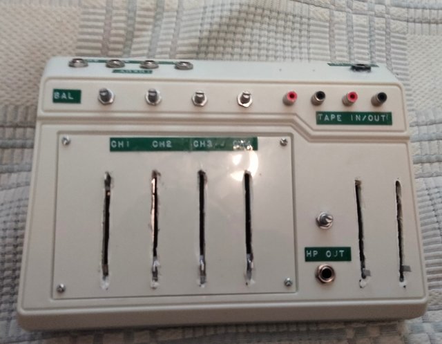
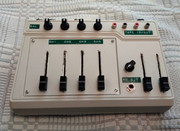
Here's the build so far :
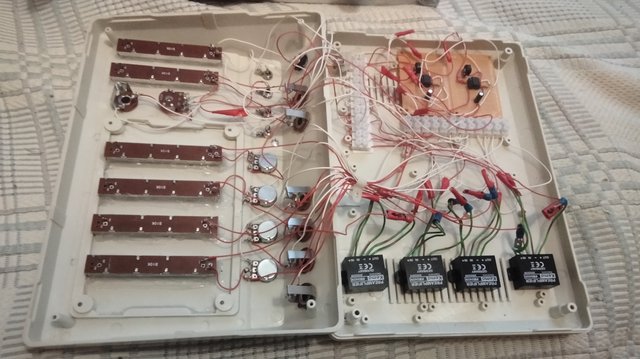
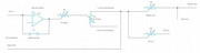
IMG-20240518-140358-01.jpg


And the insides :

IMG-20240517-150733.jpg


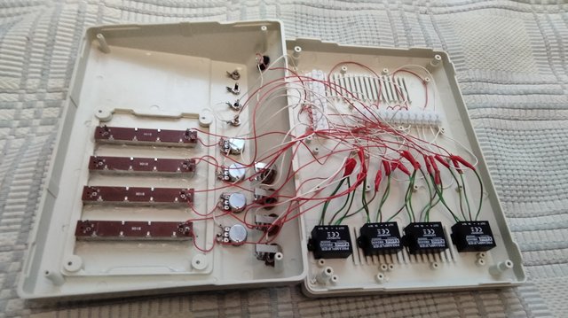
I couldn't get the preamps working so I made it passive. Also there's something wrong with the channel 4 pan (a bad pot?)

It's got 4 channels with pan control, tape in/out and HP out.

Any thoughts or improvement ideas?

-ef
 
After some soldering work I managed to put together two nearly identical line preamplifiers :

IMG-20240527-195338.jpg


Then I wired them into the build to beef up the summing bus (top right) :

IMG-20240527-213113.jpg


They have trimmers for left/right volume control. Too bad the pan controls no longer work properly, I'll look into it.
 
Here's your same schematic.....only a bit more clearer and detailed:

View attachment 129307
My version may not be completely correct as your schematic image was rather very fuzzy and it was difficult for me to exactly make out what was what!!!

/

Op Amp configuration is incorrect (looks like it is on the original but it's not really legible as you say)
 
Op Amp configuration is incorrect (looks like it is on the original but it's not really legible as you say)
[Op Amp configuration is incorrect] -- OK, fine!!! I was expecting for that to happen!!! So, just show me how things are -- supposed -- to be and I will make the corrections. NO BIGGIE!!!

By the way.....when I clicked on the OP's "Dropbox" link in Post #14, this is what I got:


1718282844313.png

I would think that the OP would cheerfully provide at least a somewhat readable version of his schematic so the rest of us would be able to follow along with whatever it is that he is attempting to accomplish. Maybe because, as he posts on May 30th, that he has finally gotten everything working (i.e., PS. I got the pan controls working / PPS. I got both master preamps working) that he no longer feels that he needs any of us "Old Audio Geezer's" for anymore help!!! He hasn't made a new posting since this past May 30th!!! Maybe this "Thread Is Dead" now. Dunno.....

/
 
[Op Amp configuration is incorrect] -- OK, fine!!! I was expecting for that to happen!!! So, just show me how things are -- supposed -- to be and I will make the corrections. NO BIGGIE!!!

By the way.....when I clicked on the OP's "Dropbox" link in Post #14, this is what I got:


View attachment 130560

I would think that the OP would cheerfully provide at least a somewhat readable version of his schematic so the rest of us would be able to follow along with whatever it is that he is attempting to accomplish. Maybe because, as he posts on May 30th, that he has finally gotten everything working (i.e., PS. I got the pan controls working / PPS. I got both master preamps working) that he no longer feels that he needs any of us "Old Audio Geezer's" for anymore help!!! He hasn't made a new posting since this past May 30th!!! Maybe this "Thread Is Dead" now. Dunno.....

/

Hi Midnight. To be clear I was pointing that out for accuracy and in case anyone misled by it. Not as a criticism. Yes - no biggie indeed.
I can't put a detailed drawing on here atm but see image pasted below. The audio signal should go into Pin 3 (+) and the Pin 6 (Output) connect back to Pin2 (-).
The Bypass Link serves no useful purpose as shown. Although the space could be used for a resistor to make into an amplifier with gain together with adding an additional resistor from Pin 2 (-) to 0V.
You'd probably also add a resistor from Pin 3 (+) to 0V to define input impedance and provide a path for dc bias (esp in case of having an ac coupled source). And an input capacitor in case you have a dc coupled source with non-negligible offset. Or to allow for "artificial" audio reference eg if powering from a unipolar power supply (eg a typical effects pedal running from a single 9V PP3 battery or DC input).
9V battery).

On the Dropbox link - yes - I got the same. Annoying tbh.

Cheers.

1718294051563.png
 
Last edited:
Here's your same schematic.....only a bit more clearer and detailed:

View attachment 129307
My version may not be completely correct as your schematic image was rather very fuzzy and it was difficult for me to exactly make out what was what!!!

/

I don't know if this is your latest schematic but it looks like you pan pot is presenting a dead short to the alternate tape input when hard panned L or R.

This might still work as most semi-pro/consumer gear uses series output resistors to protect against shorts.

JR
 
I don't know if this is your latest schematic but it looks like you pan pot is presenting a dead short to the alternate tape input when hard panned L or R.

This might still work as most semi-pro/consumer gear uses series output resistors to protect against shorts.

JR
This isn't my circuit. I was just -- replicating while clarifying -- the OP's original circuit. No updates have been posted.

/
 
I bought four 22k pots to replace the 10k ones for pan control. This is to achieve better/wider stereo image (I'll probably wire just one before doing all the channels, or test it outside the box with a spare preamp)

The schematic hasn't changed from what it is in the manual.

Here's the pdf as an attachment since Dropbox seems to be quirky to some (I originally tried to save forum space by linking the file)

One thing I'm proud of is that the unit has seemingly flat frequency response.
 

Attachments

  • district4_manual.pdf
    712.4 KB · Views: 1
Back
Top