sontec 1 RU build thread

GroupDIY Audio Forum

Help Support GroupDIY Audio Forum:

This site may earn a commission from merchant affiliate links, including eBay, Amazon, and others.
Holger said:
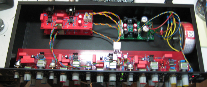
My third:

front.jpg


oben.jpg


I can really recommend this EQ. Jump on this as long as Igor stocks it...

what op amps are you using?
 
Holger said:

thanks, makes sense with their low noise floor :)

Do you also happen to have the cart of your resistor / capacitor / parts purchase for stuffing the boards?

I've seen you quite built a lot of units and all of em look really proper.

Would you mind to share the info?

-

Also Igor, I couldn't find a mono version of this EQ, nor the faceplate you are using on this build?
 
Biasrocks said:
Hoping for a quick favor from a kind soul with a working build.

I'm having some problems with my cut's / gain structure in my build.

http://www.groupdiy.com/index.php?topic=27972.msg593590#msg593590

I get healthy AC voltage on PIN 1 (Boost bus) of the I/O - EQ board connector but low voltage on PIN 3 (Cut buss) which I think may be the problem.

If you inject a line level 1khz tone on the input, with the boost/cut control centered and the EQ IN; what are the AC voltages present on PIN 1 and PIN 3. I'm guessing they should be around the same level, but I'm not sure.

This would help me track down this last gremlin.

Regards,
Mark

Have you checked the opamps yet?
 
Biasrocks said:
I get healthy AC voltage on PIN 1 (Boost bus) of the I/O - EQ board connector
Assuming healthy=unity gain, polarity inverted=0dB at pin1 with 0dB input signal feed.

but low voltage on PIN 3 (Cut buss) which I think may be the problem.
I've checked levels on each of the 20K summing resistors and when I apply full boost centered at 1khz I'm getting around 1.5Vac of signal before the resistor and about 1/10th of that after the summing resistors.
My output OPA604's are running super hot as well, not sure if that's normal.
When disconnecting the filter board, output of IC6 or XLR-out pin2 will read same level and polarity as input level and opamp will stay cool, else IC6 or servo IC10a might be blown.
What is the voltage reading at servo out IC10a-pin1? Might as well be a bad cap C62 that died from too long soldering on and servo now running open-loop.
IC6-pin3 will be close to 0V and a working IC6 will try its best to keep its inverting input pin2 (virtual ground node) at this same level as pin3, not at 'about 1/10th of around 1.5Vac'.
 
My pleasure.
Biasrocks said:
My remaining problem is an oscillation in the individual bands. High bands are more suseptible than the low bands but I can get every band ringing like a bell. High bands will start after about 3db of boost.

I'm using verified good OPA2604's for each band. I went through an added the 5pf compensation caps to each band (which Igor doesn't recommend for 2604's) with no difference. Moved wires around with no difference.

Not sure if this could this be power supply decoupling issues or more of a frequency compensation issue.
Just run the numbers for maybe CF5.1 to know why your 5pF wouldn't make a difference ... ( 1/(2PI*11K*5E-12) LPF at 2.9MHz wouldn't help that much when opamp runs out of GBW). A 47pF might be a better fit. The 12pF comp.caps C23 and C57 across the 20Ks at 660kHz are on the high side as well. Wouldn't go lower than 27pF, but as always YMMV.
 
Igor said:
Hi, I bought opa604's last time from digikey, but for now seems they
doesn't have them. Farnell is another option.
Regarding resistors, R-EU_0207/12 means 1/4w, 12 mm pitch.
I.e. common 1/4w resistor.
I used to draw pcbs in Eagle, really good prog ,but bom-wise, it is bad ;)

Pitch as in length or diameter?

what about the lead spacing?

So you are saying 0207 and 0204 are the same? 207 is just a building type and 207 & 204 are 1/4 therewith?

I thought 204 were the ones that small ones that easily roll off your board?

Mike
 
Biasrocks said:
It seems strange that no one is having this problem with their 2604's.

using LME49860 here because quite frankly OPA2604's suck. Even NE5532 sounds better, try it.

If concerned about headroom, 15V vs. 24V rails will give you a whopping 4dBu more. LME49860 can do 22V rails by the way. Excellent pairing with some decent DOA's.
 
12-5pF as in the schematic worked for all opamps I tried (OPA2604, LME and NE parts). Never had oscillation in the filter boards.

Using just about any DOA's on the I/O board was oscillating like mad. 47pF tamed them all. Maybe it was more, say 100pF. My approach was pretty hands on, increase feedback pF range capacitance as much as it takes. Filtering boards bypassed. Who cares what happens in the +200khz range, right? (apparently igor and his dolphins do)

I'm using LME parts as the servos as well by the way.

Do you perhaps have some exotic or non-standard PSU configuration that might be the cause of your oscillation problems?
 
Biasrocks said:
Nice, the GBW is almost triple that of the 2604 and the slew rate is 5/Vus slower than the 2604.

Manufacturers always lie. Testing conditions are rarely disclosed in detail. Sure you have this and that bandwidth with whatever slewrate, but at what distortion and at what frequency range.

The only thing that's reasonably trustworthy for us audio folks is Samuel Groners opamp catalog.

Biasrocks said:
We're already running very close to 22v rails with the 22 ohm PS "fuse" resistors installed, no big deal to adjust those slightly.

They are not just fuse. Standard LM regulators have white noise issues. These droppers will take care of that. Also, if using the OPA's you can tune your PSU so that rails are 24V after the droppers. (will be more like 25.5V at the PSU outputs)
 
atticmike said:
Igor said:
Hi, I bought opa604's last time from digikey, but for now seems they
doesn't have them. Farnell is another option.
Regarding resistors, R-EU_0207/12 means 1/4w, 12 mm pitch.
I.e. common 1/4w resistor.
I used to draw pcbs in Eagle, really good prog ,but bom-wise, it is bad ;)

Pitch as in length or diameter?

what about the lead spacing?

So you are saying 0207 and 0204 are the same? 207 is just a building type and 207 & 204 are 1/4 therewith?

I thought 204 were the ones that small ones that easily roll off your board?

Mike

can anybody assist me with my question ? :)
 
atticmike said:
atticmike said:
Igor said:
Hi, I bought opa604's last time from digikey, but for now seems they
doesn't have them. Farnell is another option.
Regarding resistors, R-EU_0207/12 means 1/4w, 12 mm pitch.
I.e. common 1/4w resistor.
I used to draw pcbs in Eagle, really good prog ,but bom-wise, it is bad ;)

Pitch as in length or diameter?

what about the lead spacing?

So you are saying 0207 and 0204 are the same? 207 is just a building type and 207 & 204 are 1/4 therewith?

I thought 204 were the ones that small ones that easily roll off your board?

Mike

can anybody assist me with my question ? :)

http://www2.mouser.com/Passive-Components/Resistors/Through-Hole-Resistors/Metal-Film-Resistors/_/N-7h7zb?P=1z0vod7Z1z1414h&Keyword=Xicon&FS=True

https://docs.google.com/viewer?url=http://www.mouser.com/catalog/specsheets/XC-600046.pdf&pli=1
 
What is the voltage rating for these parts of the bom?

CAPACITORS-POLY ETC.

1 0.15U C-10-15/6
2 0.47U C-10-15/6
8 1U C-10-15/6
1 2U2 C-10-15/6
1 1U C-10-15/6
2 2u2 C-10-15/6

1 4u7 C-10-15/6 (PITCH UP TO 35MM, POSSIBLE TO USE 2 CAPS IN PARALLEL)
1 ** C-10-15/6

--

Also, 1 ** is still in question

--

Also, I have issues with the 2k pf mica capacitors

CAPACITORS-SILVER MICA OR POLY

1 3n3 C-7-10/5
2 2n70 C-7-10/5
1 100P C7.5/3
1 150P C5/2.5 NOT NECESSARY WITH OPA604
2 330P C7.5/3


CAPACITORS-SILVER MICA OR COG
5 5p C2.5/2
2 12p C7.5/3

--

I'm sorry but I seriously doubt there will be a 2.7k pf mica with a width of 5 mm ...

they mostly start at twice the value (10 mm).
 
I don't think you could find any of those parts in a low enough voltage value for it to be a problem. You want to have them rated at least the amount of the highest possible voltage they will see in the given circuit. No harm in getting a capacitor rated at a higher voltage though.

Most people run into problems when they order a bunch of low voltage electrolytic and put them in a power supply rated over the max voltage of the electrolytic capacitor and before long...pop! Film and ceramic on the other-hand usually are at least rated at 50v and unless you are building some high voltage tube stuff, you are going to always be fine.
 
abechap024 said:
I don't think you could find any of those parts in a low enough voltage value for it to be a problem. You want to have them rated at least the amount of the highest possible voltage they will see in the given circuit. No harm in getting a capacitor rated at a higher voltage though.

Most people run into problems when they order a bunch of low voltage electrolytic and put them in a power supply rated over the max voltage of the electrolytic capacitor and before long...pop! Film and ceramic on the other-hand usually are at least rated at 50v and unless you are building some high voltage tube stuff, you are going to always be fine.

Well, I suppose with op-amps operating at 24v, capacitors with anything just above that would be probably fine (68V)?

And about the 2.7k pf mica with a width of 5 mm ... ? I searched mouser in every mica corner and couldn't find anything that'd match a width of 5mm.
 
Anything 35V and above should be fine for caps.

Here's a 2700pF Mica from Mouser 598-CD16FD272JO3

http://www.mouser.com/Search/ProductDetail.aspx?R=CD16FD272JO3virtualkey59850000virtualkey598-CD16FD272JO3

Charles
 
Hi all

I am trying to get one channel of the Sontec up and running. I am running into some problems with the star ground. I was under the impression that I should star ground to chassis the AC ground, PS ground and the XLR ground on the Summing board. When I did this I blew a fuse (500mA Slow Blow). If I just connect the AC ground or the AC and XLR Grounds the voltage is fine. If I try the PS ground and AC ground only it drops my voltage to just under 5V.  :-[

Yesterday when I had only the AC ground connected I was able to safely power one channel with all IC's and 2 DOA's. I will try this with now with the XLR and AC connected at the star ground.

What have successful builders used as a grounding scheme? Any help would be greatly appreciated!

Thanks, Charles
 
Hi Mark

Thanks for your response. Here's a picture of the PS. The black wire that is in the center connects PS ground to the star ground. Nut not attached in photo! As I said earlier the PS works fine unless these two points are connected and then it does not.

Because of huge heat sinks 100uF caos are mounted on the bottom.

Thanks, Charles
 

Attachments

  • PS 1.jpg
    PS 1.jpg
    296.3 KB
Double check your transformers colour coding of your center tap connection. For the usual suspects it is not black+orange.
 

Latest posts

Back
Top