Telefunken ELA M 251 Clone Tube Microphone Build Thread (D-Ela M 251E)

GroupDIY Audio Forum

Help Support GroupDIY Audio Forum:

This site may earn a commission from merchant affiliate links, including eBay, Amazon, and others.
poctop said:
The Supply for the relay is taken from the regulated heater supply so it should remains constant despite the extra draw.
Best,
dAN,
The voltage before the cable will be constant, true... but the losses on the cable will be higher, the higher the current draw...Unless there is something I am missing the cable will have 10% more losses in figure of 8 than in cardioid...
 
dmnieto said:
poctop said:
dmnieto said:
poctop said:
esistance you need to account by adjusting the heater voltage with the Voltmeter on the mic pcb itself there is a pad for such measurement on the mic pcb
[...]
the heater Voltage is regulated from the psu so this tiny pull of current for the pattern the regulator will take care of that
hope this helps,
Best,
DAN,
The voltage before the cable will be constant, true... but the losses on the cable will be higher, the higher the current draw...Unless there is something I am missing the cable will have 10% more losses in figure of 8 than in cardioid...
Yeah, I know I can adjust the heater voltage to account for losses in the cable... what I am saying is that there is going to be 100mV difference between the switch placed in cardiod mode vs figure of 8. (there will be a 350mA drain in cardioid and 416mA in figure of 8 because of the relays). I am not sure how much the tube will be affected by that though.


The Supply for the relay is taken from the regulated heater supply so it should remains constant despite the extra draw.
Best,
dAN,

The voltage before the cable will be constant, true... but the losses on the cable will be higher, the higher the current draw...

Correct,

I made a little calculation with 1.2ohm cable feed whis is probably on the high side, the worst case scenario between 350ma to 416ma figure 8.

Then Figures 8 the difference would be 79.2 mV

Then Cardiod and Omni would be  39.6 mV

Best,
Dan,

 
poctop said:
Correct,

I made a little calculation with 1.2ohm cable feed whis is probably on the high side, the worst case scenario between 350ma to 416ma figure 8.

Then Figures 8 the difference would be 79.2 mV

Then Cardiod and Omni would be  39.6 mV

Best,
Dan,

Negligible then. I understand you consider that any magnetic field radiated by the coil from the ripple of H+ will be small even close to the HiZ points.
 
dmnieto said:
poctop said:
Correct,

I made a little calculation with 1.2ohm cable feed whis is probably on the high side, the worst case scenario between 350ma to 416ma figure 8.

Then Figures 8 the difference would be 79.2 mV

Then Cardiod and Omni would be  39.6 mV

Best,
Dan,


Negligible then. I understand you consider that any magnetic field radiated by the coil from the ripple of H+ will be small even close to the HiZ points.

Voltage will stabilise once the pattern changes they should not be more ripple  in h+ as the one at the output from the psu once the Voltage is set,

Best,
Dan,
 
Any reason the pattern switch has to be shorting?

Can see a possibility where, for an instant, current is flowing to both relay positions at once, making the relays themselves act as a shorting switch. Or does it not matter?
 
Dylan W said:
Any reason the pattern switch has to be shorting?

Can see a possibility where, for an instant, current is flowing to both relay positions at once, making the relays themselves act as a shorting switch. Or does it not matter?

Supply for the relay are independently controlled via the psu switch,  current is not allowed to flow trough the unsollicited relay.
only in the case of fig 8  a pair of relay will be activated at once for cardiod and omni only 1 relay is sollicited at the time.
hope this helps,
Best,
dAN,
 
poctop said:
Dylan W said:
Any reason the pattern switch has to be shorting?

Can see a possibility where, for an instant, current is flowing to both relay positions at once, making the relays themselves act as a shorting switch. Or does it not matter?

Supply for the relay are independently controlled via the psu switch,  current is not allowed to flow trough the unsollicited relay.
only in the case of fig 8  a pair of relay will be activated at once for cardiod and omni only 1 relay is sollicited at the time.
hope this helps,
Best,
dAN,

Right, I'm just wondering whether, with a shorting switch, there may be an instant when, eg, both the cardiod and omni relays are activated, which might make pattern switching quieter.

Essentially I'm asking whether it's ok to use a non-shorting switch, since I have a few of those.
 
Dylan W said:
poctop said:
Dylan W said:
Any reason the pattern switch has to be shorting?

Can see a possibility where, for an instant, current is flowing to both relay positions at once, making the relays themselves act as a shorting switch. Or does it not matter?

Supply for the relay are independently controlled via the psu switch,  current is not allowed to flow trough the unsollicited relay.
only in the case of fig 8  a pair of relay will be activated at once for cardiod and omni only 1 relay is sollicited at the time.
hope this helps,
Best,
dAN,

Right, I'm just wondering whether, with a shorting switch, there may be an instant when, eg, both the cardiod and omni relays are activated, which might make pattern switching quieter.

Essentially I'm asking whether it's ok to use a non-shorting switch, since I have a few of those.

Ah OK i just realized what you meant ,  yes the shorting type pattern switch is all i could find for this configuration  at mouser, i was aiming at first with the non-shorting as this is what i am used to , but finally tested the shorting switch and the pattern swap was quiet and  no poping issue,  at this time both can be used without issue.
Best,
Dan,
 
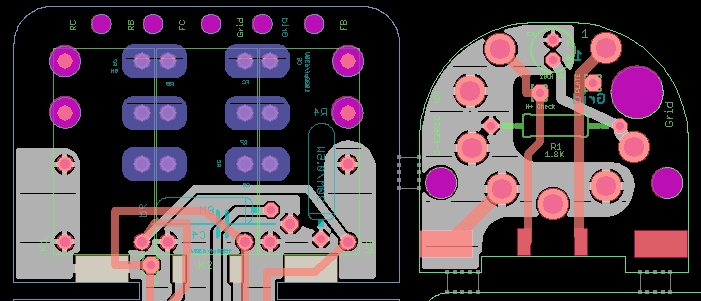
Hi All, As i have gotten a couple of PM regarding this , i will try to unconfuse folks ,

this message pertains that the Errata on the front page has been removed the inversion of C3 on the tube socket pcb has been corrected for the production run that some of you already bought , this errata only applied to those that purchased the inital proto run that was about only 10 pcb of those ,

currently the pcb that is offered is all corrected and good to go ,

here is the summary of what have been done as far of improvement or changes ,
this same pcb is the one that is currenlty available ,

Best,
DAn,

Will it be the same as the initial run or have you changed anything?

Updates Are.

Silk Error Polarity Cathode Bypass Cap  Fixed,
Relay Tightest as possible I guess  :eek:
Output Cap Receptacle Enlarged.

D251E.jpg


58d0281994127.jpg


best,
dAn,
 
Hi Guys!

I just wanted to report another build of the D-251 here!

First of all, big thanks to poctop for his efforts on this PCB design.
Very well laid out and easy to follow build.

I built this with, and as a comparison to the D-C12 microphone, which is a very straight forward build.
I actually thought this would be significantly more difficult than other DIY-projects, but it actually looks more complicated that it is.
All in all a very rewarding build that I can only recommend!

Now I only have to wait for Chungers donor bodies and transformers!

Thanks to everyone in this forum who is putting in a lot of effort and making this possible!
PCBs, bodies, transformers, capsules and custom parts, none of this would be possible without your joint efforts.
I really appreciate this.

Best,
Michael

D-251 Back.jpg

D-251 Upper.jpg

http://groupdiy.com/Users/Violator/Desktop/D-251:D-12 Upper.jpg[img]
[img]/Users/Violator/Desktop/D-251:D-12 Back.jpg
 

Attachments

  • D-251 Back.jpg
    D-251 Back.jpg
    147.3 KB
I'm gathering up all the parts for this build and was wondering if anyone had any opinions on which capsule would work best from the choices I can afford right now. Here are the choices I am considering.

1. micriphone-parts RK-12 : 3-micron Japanese mylar - $109
2. AA AK-12 : 6 micron German mylar - $99
3. Chugers 34MM Edge Terminated Capsule : unknown mylar thickness - $76

Any thoughts? Thanks.
 
ding said:
I'm gathering up all the parts for this build and was wondering if anyone had any opinions on which capsule would work best from the choices I can afford right now. Here are the choices I am considering.

1. micriphone-parts RK-12 : 3-micron Japanese mylar - $109
2. AA AK-12 : 6 micron German mylar - $99
3. Chugers 34MM Edge Terminated Capsule : unknown mylar thickness - $76

Any thoughts? Thanks.

None of them would work I think. You need a four wire capsule with isolated backplanes... At least if you want the figure of 8 mode to work
 
2 of the sites specifically mention the Elam 251 on their capsule page. Is there a way to use these at all with this pcb? Do you have any recommendations on any capsules that will work aside from beesknees, Tim or tskguy as I cannot afford any of these any time in the foreseeable future? It looks like the RK-87 from microphone parts and the AK-67 from AA have isolated backplanes.
 
ding said:
2 of the sites specifically mention the Elam 251 on their capsule page. Is there a way to use these at all with this pcb? Do you have any recommendations on any capsules that will work aside from beesknees, Tim or tskguy as I cannot afford any of these any time in the foreseeable future? It looks like the RK-87 from microphone parts and the AK-67 from AA have isolated backplanes.

They lied, they may support ELAM250, but 251 config won't work without circuit modifications.

Without isolated back-planes this is what will happen in figure of eight mode. Because the backplanes are electrically connected you will ground the tube grid, this will create a negative voltage in the grid compared to the cathode and effectively shut down any current in the tube.

I am not sure what will happen in the capsule, the front and back membranes are poralized with +/- 60V but with both of the backplanes grounded I guess that any signal will be seen as ripple in B+, I don't think it will get damaged.

So in summary, with a three wire design you lose the figure of 8 pattern. Yo wont have a ELAM 251, you will get an ELAM 250.

With a K87 capsule though, you will get back figure of eight, but a K87 capsule has a frequency response that peaks around 6dB at 11KHz, so you need to increase the EQ cap between the plate and ground to around 400pF to compensate. It is going to roll-off sharply at 12-13K, so it will lose some air.


NOTE:

Several manufacturers, choose to keep the polarization topology of the C12 (with the 9 polarization patterns) and modify the wiring of the tube for self-biasing. This is similar to Matador's approach to the C12 to ELAM, but it is different from the actual ELAM circuit that poctop implemented. There is also the difference in which the output of teh capsule is in the membranes in the C12 and in the backplanes in the ELAM
 
I have two RK-12s myself, it is certainly brighter than my Beesneez CK12 but does not sound bad at all.

The peak of the RK12 is nowhere as brutal as the K87/K67 ones.
 
Thanks for all your help and knowledge. So is the most afordable option for this mic the cek-12 from peluso? There has to be something in the $100 range that is decent.
 
ding said:
Thanks for all your help and knowledge. So is the most afordable option for this mic the cek-12 from peluso? There has to be something in the $100 range that is decent.

CEK12 is still a 3 wire capsule, and it goes for around $240. It has a significant 11Khz peak as well, higher than RK12 but not as big as the K89/69.

In all honestly... all "cheap" capsules are really similar, chunger's and RK12 are good. Never personally heard the AK-12. I have a spare RK12 that I could give out to you for a discount (I bought I matched set or RK12s a while ago, but decided to buy a Beesneez CK12 and Tim Campbell's CT12 when I got the cash for them).

I think you need to know how much you need the figure of eight to take a decision.
 

Latest posts

Back
Top