You are using an out of date browser. It may not display this or other websites correctly.
You should upgrade or use an alternative browser.
You should upgrade or use an alternative browser.
Telefunken ELA M 251 Clone Tube Microphone Build Thread (D-Ela M 251E)
- Thread starter poctop
- Start date
Help Support GroupDIY Audio Forum:
This site may earn a commission from merchant affiliate
links, including eBay, Amazon, and others.
- Joined
- Jul 15, 2009
- Messages
- 2,310
e.oelberg said:once again, do we need latching or non latching ?
Non Latching ,
Best,
Dany,
Tim Campbell
Well-known member
Andydrum82
Member
Andydrum82
Member
Andydrum82
Member
trans4funks1
Well-known member
- Joined
- Feb 4, 2013
- Messages
- 328
Beautiful!!!
Veronica Sneesby
Well-known member
- Joined
- Sep 12, 2012
- Messages
- 103
Hey, the mics are coming together nice. Thanks for sharing the photos. We love seeing you all enjoy the body kits and CK12's
- Joined
- Jul 15, 2009
- Messages
- 2,310
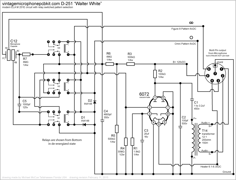
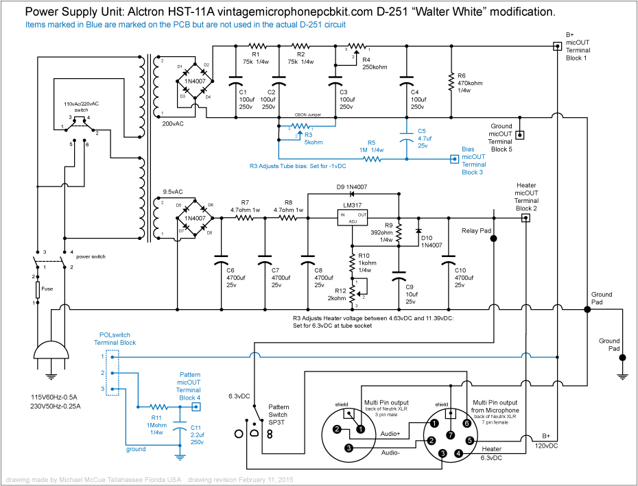
Actually there is no standard for 7 pin wiring so you can actually make your own scheme if you will
just make sure it follows the logic from the psu to the mic pcb and you will be fine ,
I just have an habit of following the Neumann scheme for my cable , I have wired my cable like this ,
but since this one have 2 pattern control it deviates a little bit from it , but as said if you are using a Gotham cable
reserve the blue wire for Circuit ground and the red wire for the heater as those are the biggest gauge to handle more current
as said you can define your own cable configuration from psu to mic as long as it is following the logic.
here is an example :
1-audio +
2-audio -
3- (Relay control 1) to OMN
cable shield = up to xlr tab as well
4-heater
5 B+
6 Pattern control ( relay control 2 ) to Fig 8 on mic pcb ,
7 circuit ground
poctop said:Actually there is no standard for 7 pin wiring so you can actually make your own scheme if you will
just make sure it follows the logic from the psu to the mic pcb and you will be fine ,
I just have an habit of following the Neumann scheme for my cable , I have wired my cable like this ,
but since this one have 2 pattern control it deviates a little bit from it , but as said if you are using a Gotham cable
reserve the blue wire for Circuit ground and the red wire for the heater as those are the biggest gauge to handle more current
as said you can define your own cable configuration from psu to mic as long as it is following the logic.
here is an example :
Perfect, Thanks a ton. I'll upload pictures after the build is complete. Should be sometime later today.
1-audio +
2-audio -
3- (Relay control 1) to OMN
cable shield = up to xlr tab as well
4-heater
5 B+
6 Pattern control ( relay control 2 ) to Fig 8 on mic pcb ,
7 circuit ground
- Joined
- Jul 15, 2009
- Messages
- 2,310
CBarx said:poctop said:Actually there is no standard for 7 pin wiring so you can actually make your own scheme if you will
just make sure it follows the logic from the psu to the mic pcb and you will be fine ,
I just have an habit of following the Neumann scheme for my cable , I have wired my cable like this ,
but since this one have 2 pattern control it deviates a little bit from it , but as said if you are using a Gotham cable
reserve the blue wire for Circuit ground and the red wire for the heater as those are the biggest gauge to handle more current
as said you can define your own cable configuration from psu to mic as long as it is following the logic.
here is an example :
Perfect, Thanks a ton. I'll upload pictures after the build is complete. Should be sometime later today.
1-audio +
2-audio -
3- (Relay control 1) to OMN
cable shield = up to xlr tab as well
4-heater
5 B+
6 Pattern control ( relay control 2 ) to Fig 8 on mic pcb ,
7 circuit ground
Please do,
we always like to see Picture of completed build here,
Best,
dAn,
Just doing some final adjustments on the PSU before plugging in. I'm noticing that the B+ voltage at terminal Block 1 is at 200v, which seems high based on what I'm reading. Using trimming resistor R4, I can get the voltage down to about 173v before the resistor bottoms out. Any thoughts here, or is sending 200v ok (I thought we were aiming for 120v)? Thanks in advance!
shaggy
Well-known member
CBarx said:Just doing some final adjustments on the PSU before plugging in. I'm noticing that the B+ voltage at terminal Block 1 is at 200v, which seems high based on what I'm reading. Using trimming resistor R4, I can get the voltage down to about 173v before the resistor bottoms out. Any thoughts here, or is sending 200v ok (I thought we were aiming for 120v)? Thanks in advance!
No load? (Mic not plugged in.)
shaggy said:CBarx said:Just doing some final adjustments on the PSU before plugging in. I'm noticing that the B+ voltage at terminal Block 1 is at 200v, which seems high based on what I'm reading. Using trimming resistor R4, I can get the voltage down to about 173v before the resistor bottoms out. Any thoughts here, or is sending 200v ok (I thought we were aiming for 120v)? Thanks in advance!
No load? (Mic not plugged in.)
Correct. While I'm posting, it seems that the mic works fine in Cardioid and Omni, but when I turn the power supply to Figure 8 I get nothing. I've checked to see that the voltage moves from pin to pin as I change polar patterns. Is this a PTP issue or possibly a capsule wiring issue?
Tim Campbell
Well-known member
Or a short between the backplates.
trans4funks1
Well-known member
- Joined
- Feb 4, 2013
- Messages
- 328
I revised the schematic drawings today to display poctops wiring pin out suggestions.


As always, if someone notices a need for a correction or edit in the drawings please send me a note so that I can make them as accurate and useful as possible.
Thank you.


As always, if someone notices a need for a correction or edit in the drawings please send me a note so that I can make them as accurate and useful as possible.
Thank you.
mgronroos
Well-known member
I agree that we could need some easy-to-read wiring diagrams for all the projects that require an extrernal PSU.
It is not that many mics, so I think it would be manageable to make one for every type.
I wouldn't have felt secure about the wiring of my 251 if it wasn't for your schematic drawing, Trans4funks1, so I very much appreciated it. Thx Again!
And feel free to post your revised version when they are done since I am about to build two more of these babies.
Cheers!
//Michael
Similar threads
- Replies
- 415
- Views
- 120K
- Replies
- 12
- Views
- 7K
- Replies
- 940
- Views
- 254K
- Replies
- 56
- Views
- 40K
- Replies
- 832
- Views
- 233K


![Soldering Iron Kit, 120W LED Digital Advanced Solder Iron Soldering Gun kit, 110V Welding Tools, Smart Temperature Control [356℉-932℉], Extra 5pcs Tips, Auto Sleep, Temp Calibration, Orange](https://m.media-amazon.com/images/I/51sFKu9SdeL._SL500_.jpg)


