Telefunken ELA M 251 Clone Tube Microphone Build Thread (D-Ela M 251E)

GroupDIY Audio Forum

Help Support GroupDIY Audio Forum:

This site may earn a commission from merchant affiliate links, including eBay, Amazon, and others.
kcguitar said:
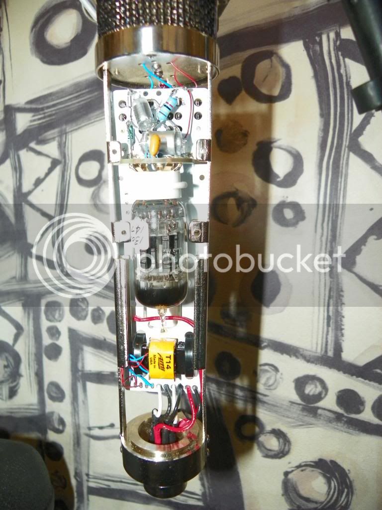
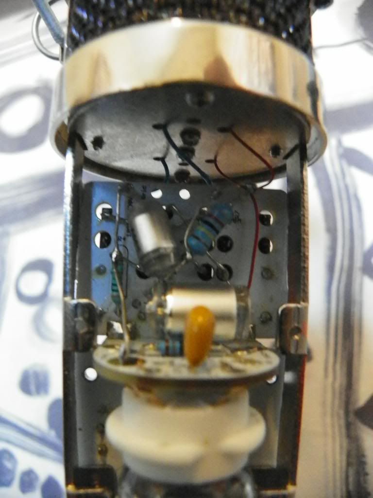
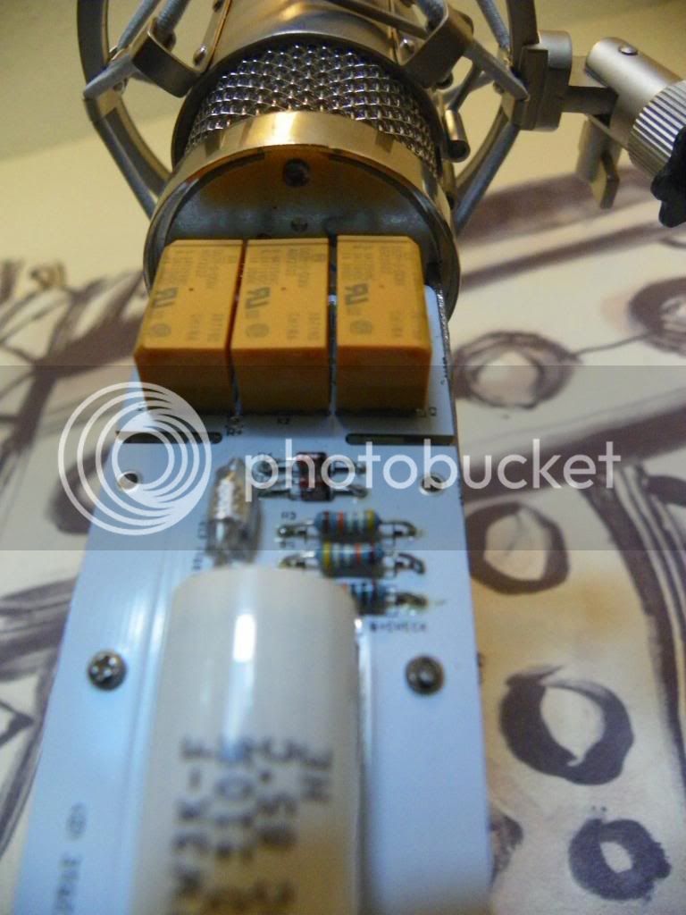
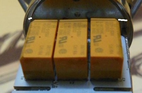
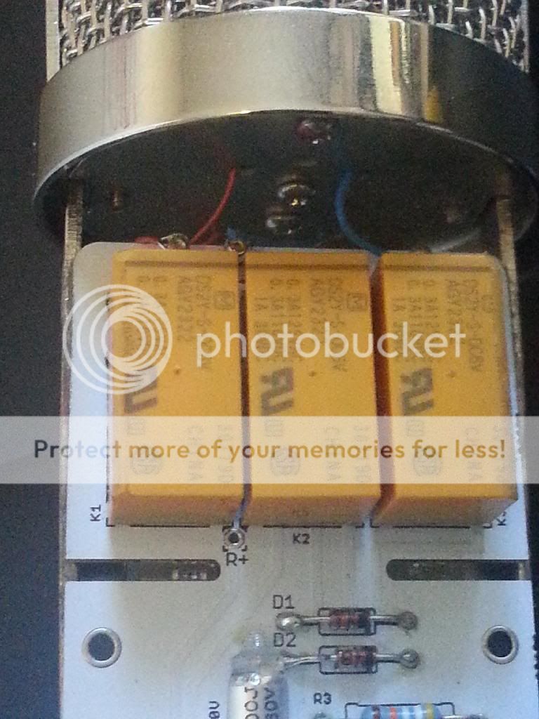
After building 2 fantastic Tim Campbell equipped sounding ELAM's this past weekend, I just wanted to mention that with the HT-11A bodies, the relays are a VERY tight fit and the 2 outside ones will rub against the body tube.  I was somewhat able to alleviate this by angling the 2 outside relays in so that their outside corners sat a little closer towards the center K2 relay.  Also I cut the leads for C4, R6, and R4 short enough that they did not protrude through the board so that they relay wouldn't have to sit any farther out than it needed.  Finally I was able to carefully file the corners of the relay in at a 45 degree angle.  My boards still flex just a bit when assembling the mic from the relays hitting the body tube though  :-\

Anyways hope that helps with anybody that has yet to use these boards in conjunction with the HT-11A's. 

would you be able to post some picture of this achievement in my case i did not have to file anything to make it fit, lets make sure when you install the relay that they are fully engaged and as close as the board as possible and not slighlty crooked , it is very easy to leave a gap there or position the relay just sidewayss,  what i usually do is that i solder one pin of the relay and then heat it up again and push down on the relay to give it his proper position and then i solder the rest of the pins, also make sure your ouput cap is not too fat to make the board flex when you install it , I agree tough it is a close fit but it should slide in properly as in my build.
also make sure the orientation of the pcb is not slighlty deviated also  cause i also notice once that the rail on the HT-11A can have a slight tolerance sideways that you can fix by just pusing them straight. once this is perfectly straight it should slide in but it is indeed a very close , so you have to make sure all the small details are on your side.  ;)

Again, Congrats for your build and i would be delighted to see picture of those babies on this thread,  :) :) :)

and an audio sample would just be divine with CT inside

Best,  :)
Dan,


Dan,

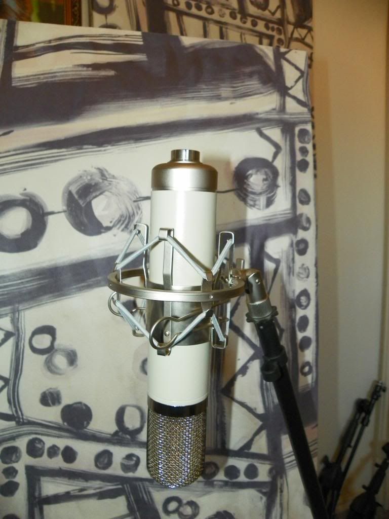
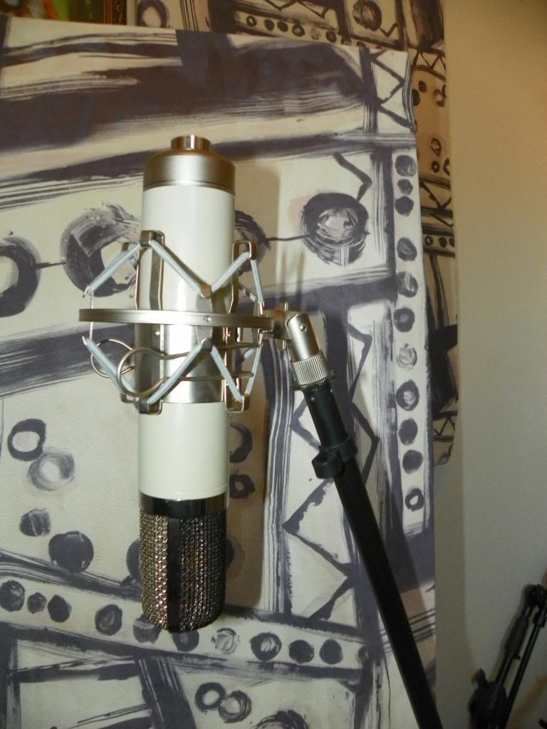
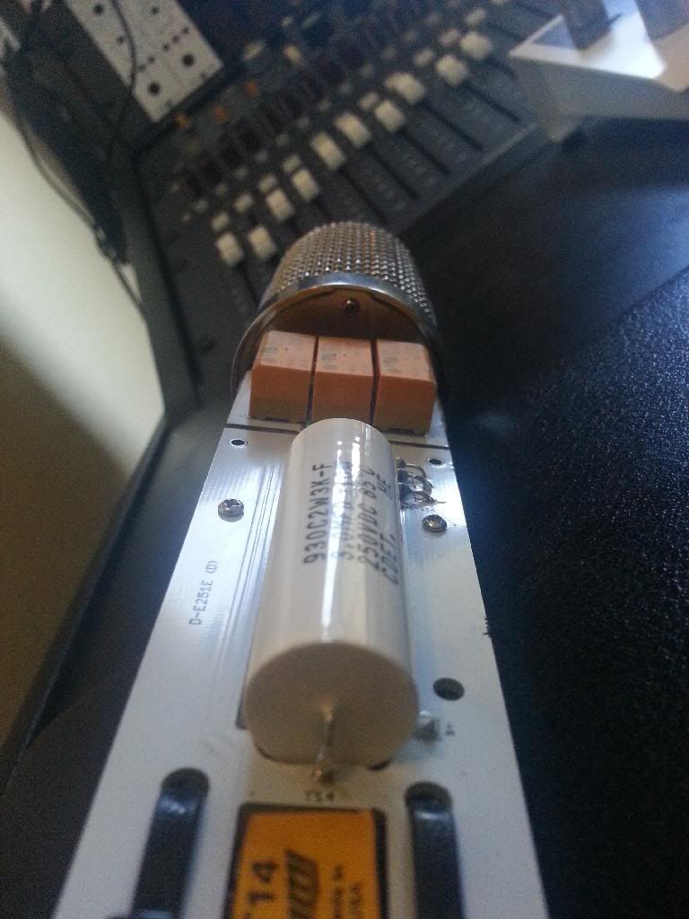
The relays were mounted absolutely flush against the board, and the board aligned with the frame rails.  I also dremeled out space for the output cap so it doesn't touch at all.  The mic pictured is my first attempt, but my 2nd one that went smoother (but still touching and with the angled relays) was already sent off to a friend before I could take pictures.  I also noticed that the mounting tab was also a culprit.  After carefully using pliers to angle the board closer to the frame rails towards the headbasket, it helped a bit as well.  You can see in the last picture how close the top outside edges of the relays come to where the body tube fits in the headbasket.   

Anyways here's my build...no clips as of yet.  I just did a comparison with my C12 TC build and noticed the ELAM had more proximity/bass response, as well as a slightly mid scooped sound that I suppose would deem it more aggressive compared to the more neutral C12.  I'll try to have a singer in soon to do some more comparisons to post.

Kevin


Many thanks Kevin for your post , Not that i want to be too fussy  ;) , but i can notice on your build that the railing and spacing is not symetrical ,
Like I said if you align it perfeclty straight it will go in without having to modify anything ,  and also not sure if you have used the same cap as i have in my picture but this one is definetly a little too fat and comes in contact with the tube , i replaced this one in the bOM for a little smaller ones that is 3.3uf polyester that will fit in no problem. but I might see if i could make even more room for this particular one in the release revision as it is rolling out now and caps is a matter of taste and fit.
on another note what i did to be able to install the 2 screws as one thread is on the other side I used a pair of plier and bent the ears a bit so i could reach the thread on the other side of the mic body  ;)

Again Really appreciate your input and hope you will enjoys these , wow 2 already. :)
Best,
Dan,

Caution to Symetrical pcb installation ,
58d0281994058.jpg


Sorry Dan.  It's aligned.  You can also see where I routed out the space for the fat cap.  Anyways all is well and it sounds great so that's all that matters I guess.     


And thanks Melodeath...I actually had them powdercoated.
 
Melodeath00 said:
So how do you plan to attach the PCB?

Looking at the 2 main mounting holes that DAn used on the Alcatron body (the two nearby the top of the cap), they are almost adjacent to the middle tapped holes on the BN rails. I'm thinking with a little more downwards adjustment and a couple of little metal tabs, should be able to make a nice sturdy mount.
 
kcguitar said:
Sorry Dan.  It's aligned.  You can also see where I routed out the space for the fat cap.  Anyways all is well and it sounds great so that's all that matters I guess.     


And thanks Melodeath...I actually had them powdercoated.

Awesome Kevin , you are right , i am just aiming to make the best changes to the pcb i can , i will definitively look into creating that space for the fat cap ,
Thanks For your input in this project, :)  i will also recheck mine to make sure i have not overseene somthing ,

Best,
Dan,
dD
 
 
Dan,

If there's room to extend the cap spacing to 48-50 mm, there are some interesting looking, super inexpensive Soviet mylar caps on ebay. One audiophool site says they're in between modern mylar and PIO... who knows, but worth a try.

http://www.ebay.com/itm/3-3uF-160V-PETP-Capacitors-K73-16-Lot-of-50-/400508921279
 
Dylan W said:
Dan,

If there's room to extend the cap spacing to 48-50 mm, there are some interesting looking, super inexpensive Soviet mylar caps on ebay. One audiophool site says they're in between modern mylar and PIO... who knows, but worth a try.

http://www.ebay.com/itm/3-3uF-160V-PETP-Capacitors-K73-16-Lot-of-50-/400508921279

I will try to do my best ,  ;)
DAn,
dD
 
Kevin you were Right all along , I dissambled to mic to make sure I wasnt crazy  :eek: , and understood that the first time i tried to put the sleeve the fat cap was in there too ! ,
so i tought that this was the only reason why it wouldnt but nop in, However been ale to assemble to whole mic with no mod just by prying a little bit on the rail and headbasket togheter I am even thinking that is is (actually a good thing) rendering the mic body less microphonic in regards to the Shell  ;) at the end but it still bends a bit so i removed the cap and tried again and it bent still a little hair. i Have check upon reducing the spacing on the relay position but even still the sleeve will be rubbing just a tiny glimpse ,  so smoothing the edge should be fixing the issue ,

I am checking on opening the output cap a little more still  :eek:  Space is a Premium !

thanks to Dremel  8)

Thanks Again For pointing this out ,
Best,
Dan,


No problem at all Dan!  Glad to help the community out on this first run of ELAM's with the integral switching relays.  (Those TC capsules were waiting over a year for these boards to finally come out!)
 
^^^ Thanks heaps for this DAn, and for measuring the plate current.

So obviously the total current draw entered in the excel here is the plate current (0.50mA) plus the 6072 heater current (0.35mA) = 0.85mA yeah?

8)
 
Woot said:
^^^ Thanks heaps for this DAn, and for measuring the plate current.

So obviously the total current draw entered in the excel here is the plate current (0.50mA) plus the 6072 heater current (0.35mA) = 0.85mA yeah?

8)

Nop this will be only for the B+ line from the traffo 200V , No heater current there  0.85ma  ( 0.5ma B+ and 0.35ma bleeding trough the 470K resistor of this same line,

the heater current is on the second system where usually the 9.5V attached,

Note that the heater current is 350ma and not 0.35ma  ;)

Best,
Dan,
 
poctop said:
Woot said:
^^^ Thanks heaps for this DAn, and for measuring the plate current.

So obviously the total current draw entered in the excel here is the plate current (0.50mA) plus the 6072 heater current (0.35mA) = 0.85mA yeah?

8)

Nop this will be only for the B+ line from the traffo 200V , No heater current there  0.85ma  ( 0.5ma B+ and 0.35ma bleeding trough the 470K resistor of this same line,

the heater current is on the second system where usually the 9.5V attached,

Note that the heater current is 350ma and not 0.35ma  ;)

Best,
Dan,

Where is the headslap emoticon ??    ::) this'll do.... ha ha

Got you.... was scratching my head about where the extra 0.35mA came from....
 
As I received many PMs on this , here is the status.

I currently am polishing the last details on this project , please post on this thread if you would like to be enlisted for the next run as the qty will be limited,
thanks
Best,
Dan,


Latest posts

Back
Top