The official GroupDIY 511 Help & Support Thread

GroupDIY Audio Forum

Help Support GroupDIY Audio Forum:

This site may earn a commission from merchant affiliate links, including eBay, Amazon, and others.
geoff004 said:
It's like the unit is a tad longer than most.
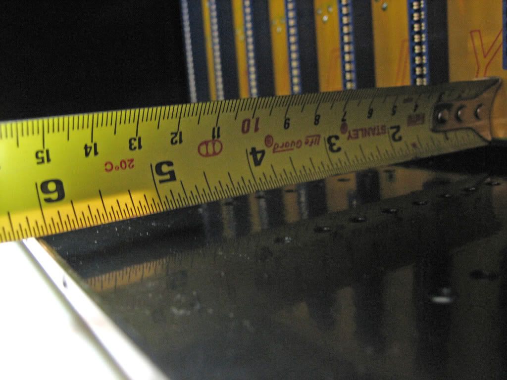
Can you measure the module for us? It should be 5-15/16" from the back of the 1/8" faceplate to the back edge of the PCB where the gold fingers are at.

Or like the rack is a tad shallower than most.
I doubt this. When we started this endeavor...we did extensive research using the VPR guidelines and measuring not current production API racks but BAE and of course my console. My 51x rack measures 6-1/8" from the where the back of the module faceplate mounts to the inside or card edge side of the PCB. FWIW, the eq section of my console measures 6-1/16". This Chandler piece would never fit in my desk!

Best, Jeff
 
I didn't want to pull the pre from the rack, just because it's a pain to stuff in there.
But I can tell you the chassis is 5 3/4" from the backside of the face to the end of the chassis.
By my rough measurement it's 5 5/8" from the front edge of the rack to the edge-card connector.  This would account for the different of about 1/8" gap.
The screws reach fine - i'm just trying to figure out what to stuff in the gap between the pre and the rack.
Can someone else measure this just so I know I didn't screw something up in assembly (which I wouldn't be surprised if I did)?
 
Anyone come up with a good part number
for the jumper headers  caps ?
the 3M recomendation was helpful but digikey
has a few different ones , tia

So as NOT to add more posts , i'll modify this one
some digikey #s i have are
2pin  3M9447-nd
3pin  3M9448-nd
shunt  609-3121-nd

these are some form of gold flash or ???
with 2.54mm pitch but may be a little shallow
pin wise for the pcb  , although if it's plate through
should not be a factor ?
for the stereo link & ground select
 
okgb said:
Anyone come up with a good part number
for the jumper headers  caps ?
the 3M recomendation was helpful but digikey
has a few different ones , tia
I email one of the fellas the best numbers. I will see if I can dig that up. You do mean for the stereo link and shunts right Greg?
 
I used Mouser part # 517-647-02-36 for the pins. They're plenty long but the gold plate is only 10u, if that matters to you. 30u plating looks/feels much nicer but I couldn't find them w/ longer pins.
 
[silent:arts] said:
geoff004 said:
since this thread popped up again-
would someone please measure the inside depth of the rack?

after some research I think your problem might be germanium module ?
is this correct ?

It might just be.
But there's a difference in other 500 series chassis verses the GroupDIY box, as the Chandler fits fine in the others.
Unless I really screwed something together wrong.
I'm just looking for a definitive answer.
 
geoff004 said:
It might just be.
But there's a difference in other 500 series chassis verses the GroupDIY box, as the Chandler fits fine in the others.
Unless I really screwed something together wrong.
I'm just looking for a definitive answer.
mhm. you can screw a lot wrong, like I did ;D
but not the depth of the backplane.
or did you mount the back metal inside of the rack?
do you have any any other (except chandler) modules to check?
the only difference between 500 and 51X is the 18pin card edge connector.
which is a problem with some fully enclosure modules.
 
geoff004 said:
[silent:arts] said:
geoff004 said:
since this thread popped up again-
would someone please measure the inside depth of the rack?

after some research I think your problem might be germanium module ?
is this correct ?

It might just be.
But there's a difference in other 500 series chassis verses the GroupDIY box, as the Chandler fits fine in the others.
Unless I really screwed something together wrong.
I'm just looking for a definitive answer.
Well, the 51x rack measures 1/16" deeper than my console. Is it possible that your XLR's do not fully seat thru the back metal? This would effectively move the backplane forward by enough to be a problem.

Jeff
 
I went back thru my emails and found Cemal's notes of a 155 to 155.5mm of depth from PCB to front of rack where back of modules mount. 155mm converts to 6.102". As you can see I am a smidge over 6 3/32". So, essentially dead on. BTW, Cemal's information came from an API 6 space lunchbox that he reverse engineered.


(click me)

PS: I could have flipped the tape over and measured in mm but where would the fun be in that!  ;D 25.4 is our friend.  8)

Geoff, if yours does not measure like this, something is off with the assembly. Let us know. I would be curious to see that Chandler module that is giving you the trouble.

Cheers, Jeff
 
Or the edge connector wasn't seated all the way to the backplane. I assume you tried the module in another slot to rule that out.
I've had some that just barely fit one way or the other but haven't had one totally bottom out with 1/8" still to go. I'm guessing if the module was that much longer, we would've heard about it before now.
 
Thanks for the measurement, Jeff.
My rack does measure out the same.  Also, my gap is probably closer to 1/16", but it's definitely there.
As for not having the edge card connector seated flat, count that out.  Besides, it'd be hard to have it off the PCB equally from top to bottom.
And again, my other units fit perfectly.  It seems that there are aspects to putting the rack together that would make it difficult to accurately put the box together wrong - that is, have it perfectly square and even, but with things not quite where they belong.

Does any one else own a Germ500 or other Chandler module?  My guess is that all the Chandler modules are the same dimension.
 
Could someone measure from the end of the edge card connector to the front of the rack?
My measurement is a hair over 5 5/8".
Is it the same on a Lunchbox or other similar rack?  Perhaps someone could measure their lunchbox if they've got one.
Are the dimensions of the edge card connectors used in the DIY rack the same as the what's used in an API rack?

I'm still trying to figure out where the discrepancy is.
Thanks.
 
Geoff,

You are dead on with a heavy 5 5/8". In a perfect world, it is 5.64" (+/- .01") from the front of the card edge connector to the mounting surface for the modules.

I remember reading a thread over at gs where a guy was having trouble with a Chandler pre fitting in the 9th or 10th slot of a Purple Sweet Ten rack. It had something to do with the full metal enclosure that Chandler uses and the extra edge connector that is in that spot on the backplane. It is possible the back of the enclosure is hitting the bottom of the longer 18 pin edge connector. You will have the same thing if you put a 550a or 550b into an 18 pin connector. If this is the case, which it sounds likely, you have 3 options as I see it.

1st, you could remove the metal enclosure from the Chandler piece.
2nd, you could notch the back bottom of the metal to drop over the longer 18 pin connector.
3rd, you could replace that particular edge connector with a 15 pin card edge connector.

Here is the gs thread.

Again, please keep us posted as this will be important info for many guys.

Cheers, Jeff
 
jsteiger said:
I went back thru my emails and found Cemal's notes of a 155 to 155.5mm of depth from PCB to front of rack where back of modules mount. 155mm converts to 6.102". As you can see I am a smidge over 6 3/32". So, essentially dead on. BTW, Cemal's information came from an API 6 space lunchbox that he reverse engineered.


To be pricise I have got the information from the original drawing of a 500 series API Eq module. During the design I cross checked all the dimensions with Volker who has the original API rack. In fact on the final production I made the depth 0.5mm to 1mm deeper (as tolerance). And this is without the thickness of the paint taken into account.

As Jeff mentioned above if the xlr connectors are not inserted/soldered to full depth it will push the pcb forward. And that is why I gave particular instructions for the assembly of the pcb-connectors and back cover at the beginning of this thread.

However, in the first two production samples the depth was under by 0.5mm. In order not to waste them we made a gasket to go between the back cover and case to increase the depth. These were supplied to a particular individual and the rest of the production was  made to the final specs. So if you find particular modules not fitting, a similar thing can be made. You can even do that by using washers.
 
Back
Top