V-241 from scratch

GroupDIY Audio Forum

Help Support GroupDIY Audio Forum:

This site may earn a commission from merchant affiliate links, including eBay, Amazon, and others.
The shielding doesn't absorb the magnetic field, it conducts it around the object in question.

Right - it re-directs it. I wonder if the thickness of the shield isn't important. I think of it like insulation but that might be wrong. 
 
I wonder if the thickness of the shield isn't important. I think of it like insulation but that might be wrong.
I think it's more like resistance (Insulation is very high resistance) and the thickness is important, good quality transformers have thick cores.  MuMetal, being such an efficient conductor of magnetic flux, can be much thinner than iron for the same degree of shielding.

I carefully emery papered the surrounding aluminium
W6A93Jy.jpg


First coat of primer (water based)
VydIg9U.jpg


DaveP
 
Hi Dave!
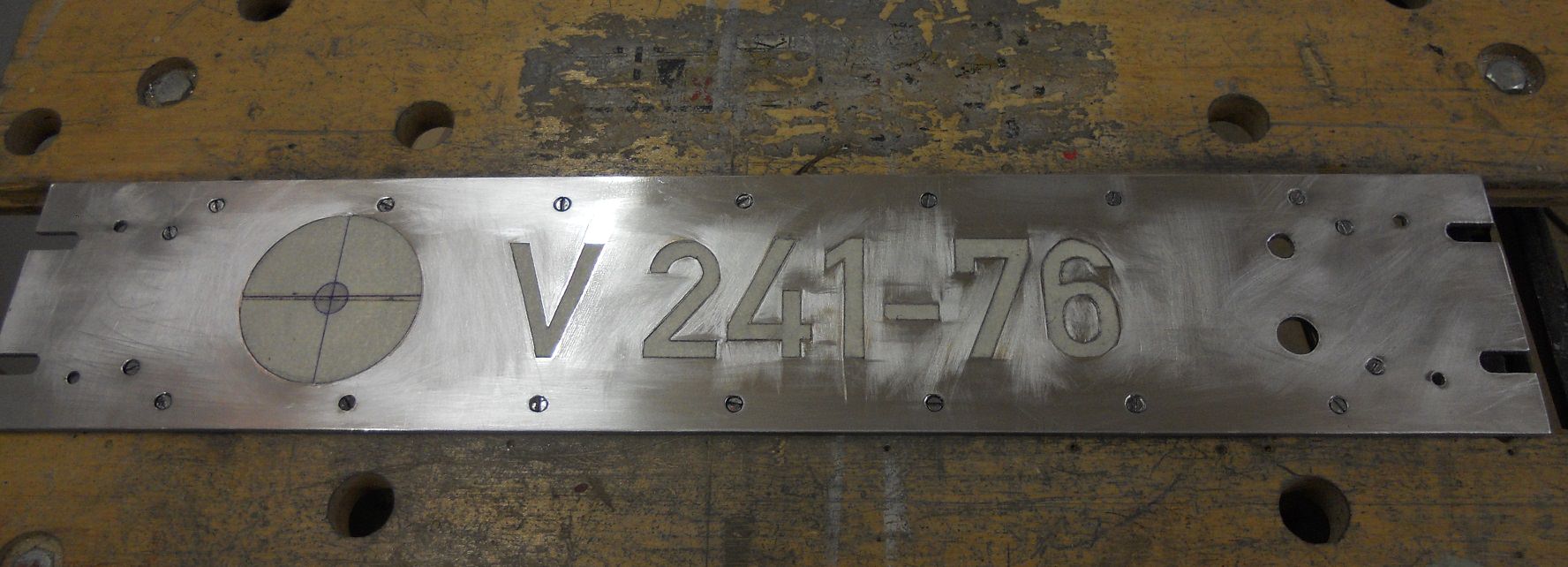
What you call pre-war font is actually today´s german licence plate font.
But I don´t think you need a registration for that pre-amp ;)

Btw. the masking looks good!
 
I put on 3 coats of blue paint, rubbing down with 1000 grade wet and dry paper in between coats.

Then the moment of truth, taking off the tape!

v22Ggqn.jpg


Not a very clear photo but I'm pleased with the result.

Then I mounted the rest of the components.

9s263QD.jpg


There is an unavoidable reflection by the gain switch as it's a mirror finish.  When I have added the gain lettering, the whole front will be given a coat of varnish to bring back the gloss and protect the surface.

DaveP
 
There seem to be around 100 people following this thread, so my apologies to you all for the time that it's taking.

There are two reasons for this:  First of all I am heavily involved with renovating our house and the wife wants it finished.  You all know where that's at. ::)

Secondly, there is only me to solve the problems.  Teams can sort things out quicker, but I have to wait for inspiration.

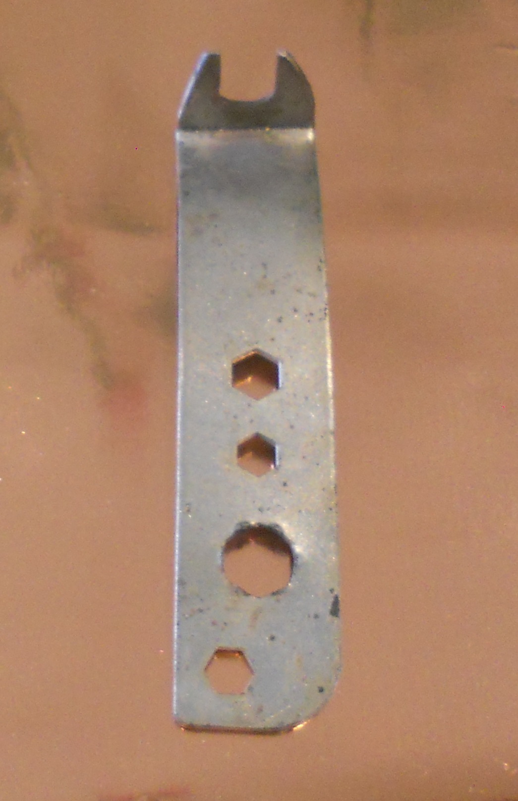
Anyways, this is how I solved the problem of tightening the back nut on the power switch.  I bent an old spanner and cut the jaws out to fit, works a treat.

nEehL61.jpg


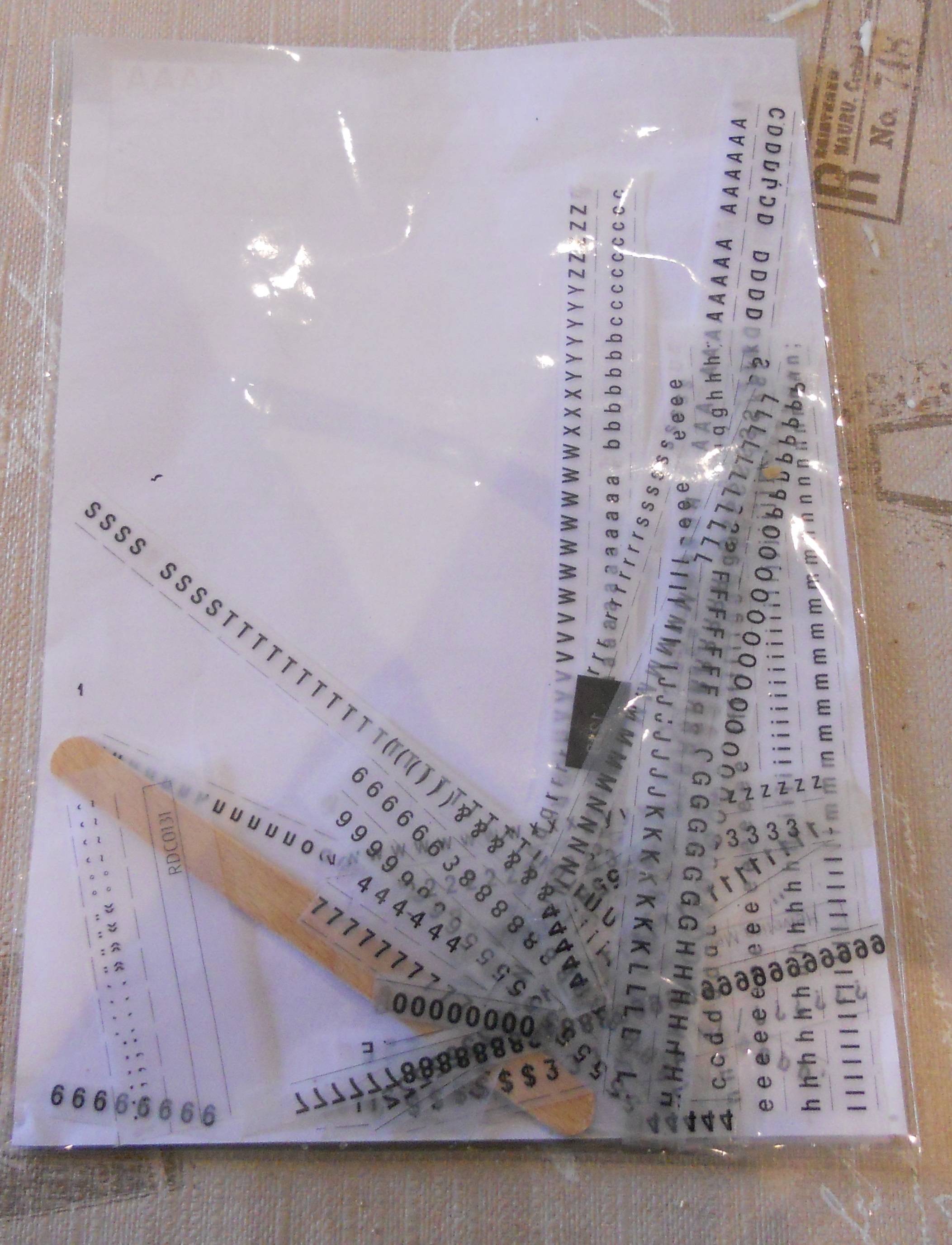
The lettering was done with Letraset

Dm1uCKb.jpg


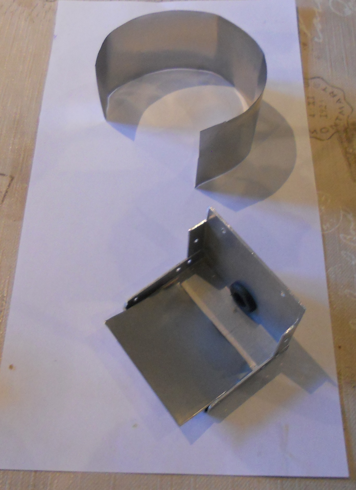
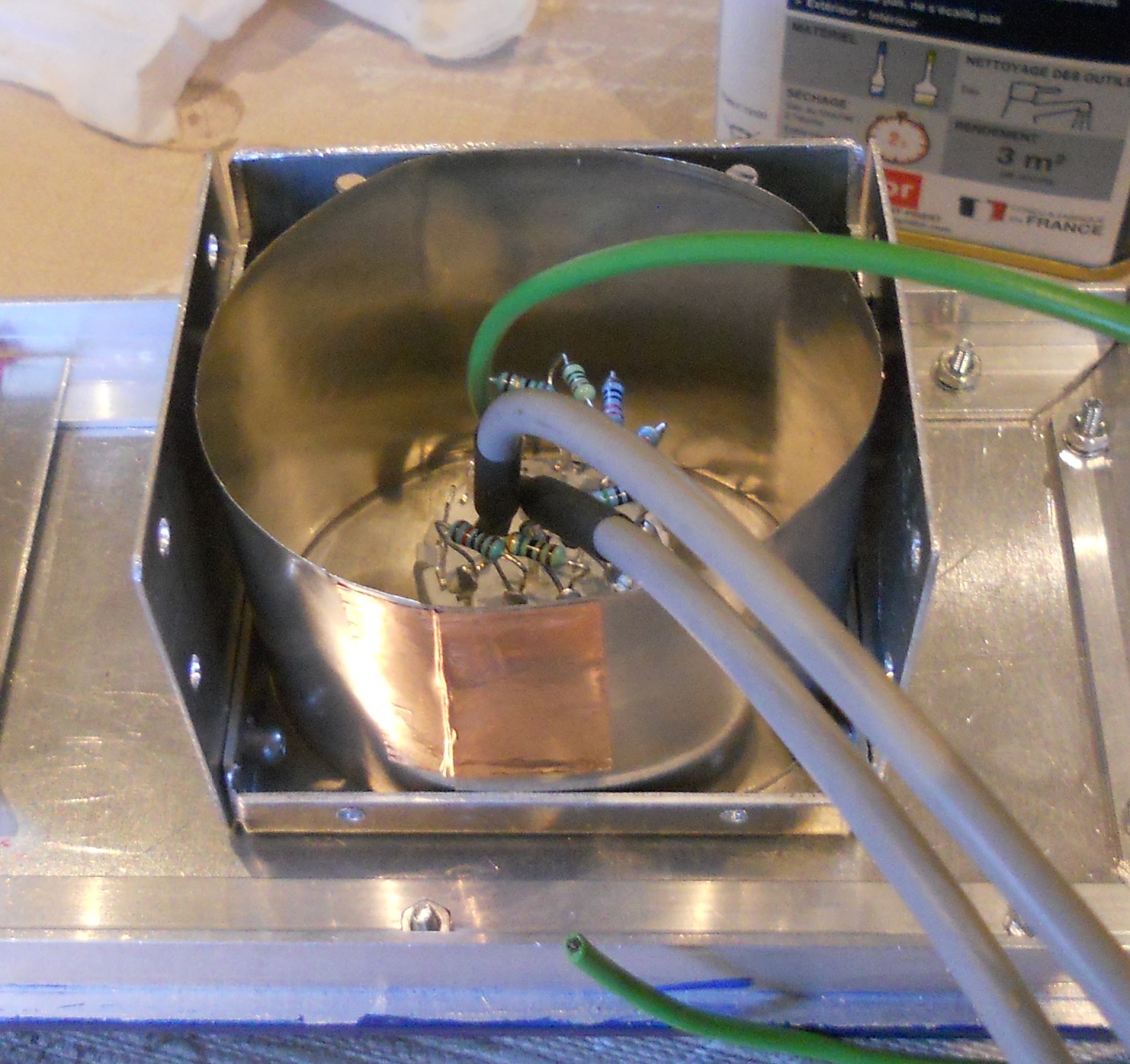
After making paper templates, I cut the MuMetal sheet to size to line the Gain switch box.

GK9HaxB.jpg


A nice snug fit held in place with copper foil

bJa14Qm.jpg


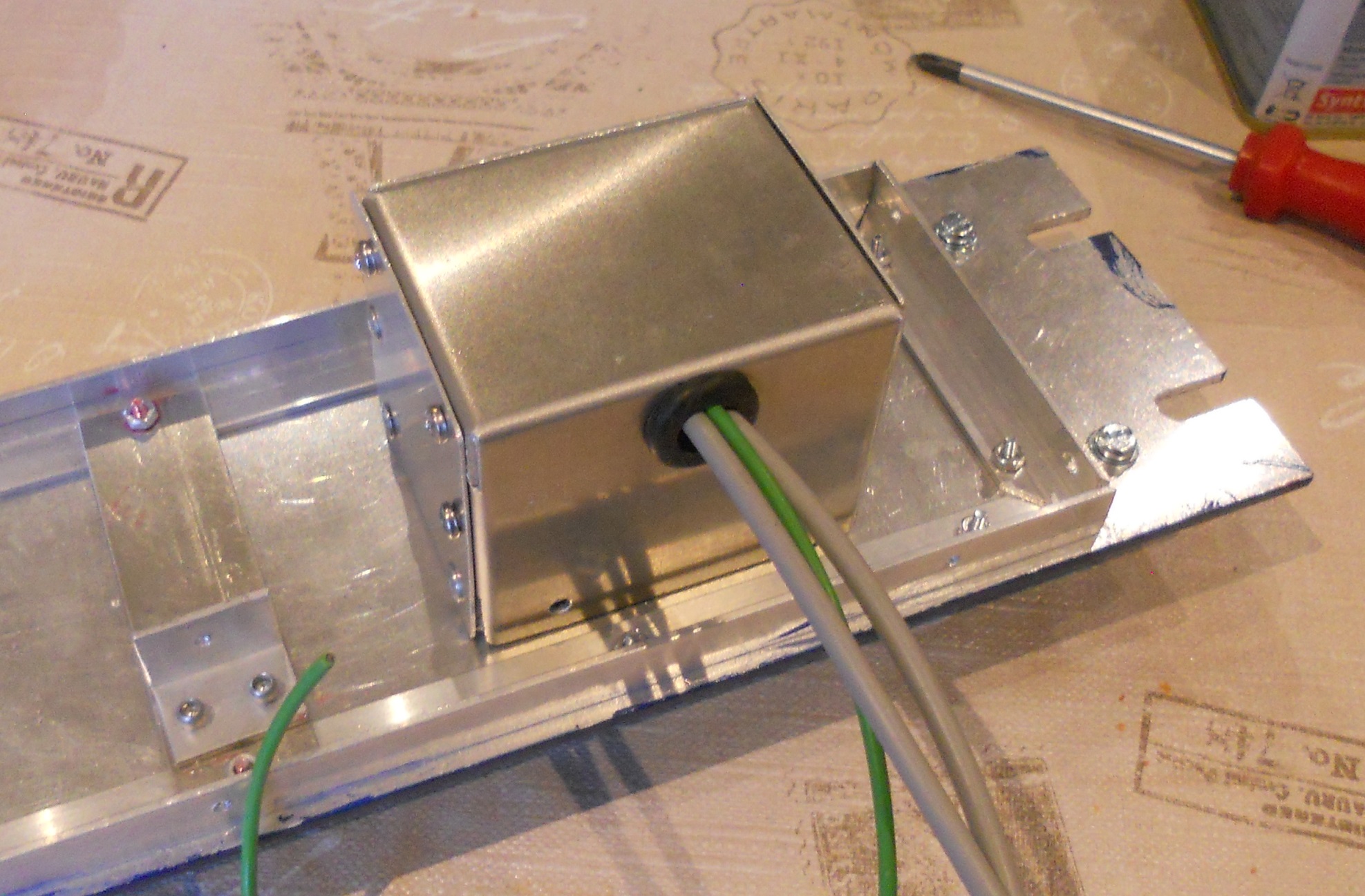
Finished Gain switch box

vxYS7rv.jpg


The front panel is in the process of being varnished.

More soon.

DaveP
 
Finished Front Panel

M0szhQf.jpg


The vintage gain control knob came off a 1950's Edwards vacuum meter, it has a chrome pointer which is not visible in the pic.  I will never be able to get another so this mic-pre will be unique.

The next task is to connect the front to the rest of the amp and finalise the connections.

DaveP
 
For shielding the gain switch you may not need mumetal - simply using copper or aluminum might be good for RF shielding.
And putting a full layer of copper around the mumetal might be worth it since the copper stuff is cheap and is a added conductive layer
Magnetic shielding needs the high permeability stuff, which you want to put around transformers that either emit or pickup hum.

This has a good description of RF shielding and magnetic shielding
https://en.wikipedia.org/wiki/Electromagnetic_shielding

 
DaveP said:
......The reason why you can use this lower level of inductance is because the twinned ECC85 has an rp of around 9k,  instead of the very high rp of a pentode.  I have tested it and it's flat down to 10Hz..

How do you did that test??,

How Could I do this test?, could you describe for us the Mortals please??..

Thanks anticipated
Opacheco
 
DaveP said:
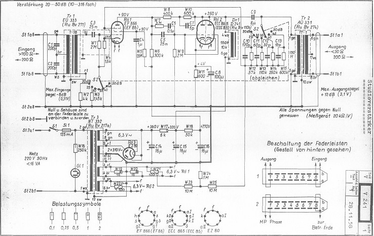
......At the output things are reversed as the ratio is 17:1 so the impedance ratio will be  289: 1.  If the load is 200 ohms, then the amp  will be working into 289x200 = 57.8K  The maximum output voltage is stated at 3.1V, so at the anode/plate it will be 17 x 3.1 = 52.7V

Dave,
Could you explain us how did you get this 3,1V figure in the output winding transformer ??

Thanks
Opacheco.
 
@Opacheco
How do you did that test??,
You need a signal generator and an oscilloscope.
Connect the Sig Gen to the input of the amp and the scope to the output.
You can measure the height of the sine wave on the screen or just look at it against the grid pattern as you vary the frequency.
Just remember that voltages read from the scope screen are Peak to Peak so you divide by 2.828 to get the RMS voltage.

Could you explain us how did you get this 3,1V figure in the output winding transformer ??
The maximum output voltage was stated on the  original schematic.

8LN0QJA.jpg


This corresponds to the maximum input 0.31V with the gain on 20dB.

You can use Google translate from German to Spanish or English

Best
DaveP

 
DaveP said:
@OpachecoYou need a signal generator and an oscilloscope.
Connect the Sig Gen to the input of the amp and the scope to the output.
You can measure the height of the sine wave on the screen or just look at it against the grid pattern as you vary the frequency.
Just remember that voltages read from the scope screen are Peak to Peak so you divide by 2.828 to get the RMS voltage.
The maximum output voltage was stated on the  original schematic.

8LN0QJA.jpg


This corresponds to the maximum input 0.31V with the gain on 20dB.

You can use Google translate from German to Spanish or English

Best
DaveP

DaveP,

Thanks a lot for your explanation time and help!!.....all is clear now.

Sorry but I will do another questions soon

Best regards

Opacheco
 
DaveP said:
The vintage gain control knob came off a 1950's Edwards vacuum meter, it has a chrome pointer which is not visible in the pic.  I will never be able to get another so this mic-pre will be unique.

Like these on ebay? https://tinyurl.com/ybb6d69v
 
Exactly! ;D

It was the chrome pointer that gave me the idea of doing the letters and dial as polished alloy.

As I only had one of these it seemed made for the job.

Thanks
DaveP
 
DaveP said:
Each dropper resistor is 2.7k and the reactance of 180uF is 17.7 ohms so each stage is a voltage divider.........

Interesting Formula!! but Do you think the Frequency would be 100Hz instance 50Hz for the calculations (rectifier effect)??, do you??

Opacheco.
 
Do you think the Frequency would be 100Hz instance 50Hz for the calculations (rectifier effect)??
If you look at a 50Hz sine wave that has been rectified, it has two peaks/second = 100Hz

https://en.wikipedia.org/wiki/Rectifier

DaveP
 
DaveP said:
The chassis design and build is finally finished.

2wn2yk0.jpg


xm1h8l.jpg


Design from scratch takes a lot of time and thought, wiring in all the components is the easy part, which is what I'm looking forward to next.

DaveP

Awesome work!

What kind of wires do you use and where do you got?

Opacheco
 
Back
Top