DaveP said:It's RS tin plated equipment wire in various colours, .
Dave
Thanks DaveP
Do you have a source for them??
Opacheco


DaveP said:It's RS tin plated equipment wire in various colours, .
Dave
DaveP said:As I said, it's RS a UK company.
http://export.rsdelivers.com/
But you may find it easier to order from the US or Mexico if these are difficult to source in Honduras
DaveP
DaveP said:Well spotted Guavatone,
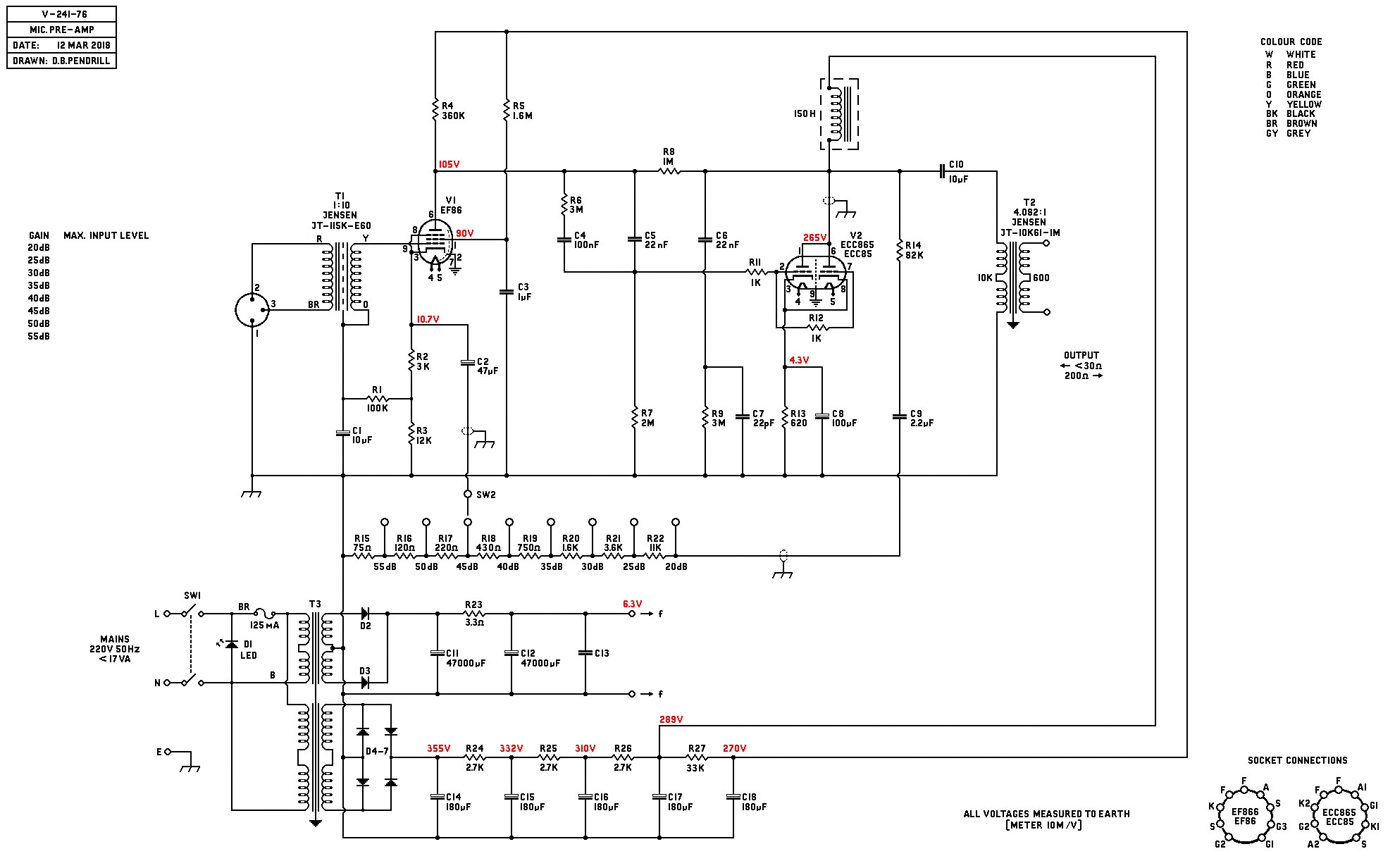
The reason for these small changes is because I have incorporated part of the V76 input circuit into the V241.
The published noise for the V241 is about -69dB whereas the V76 is around -118 to -120dB depending on the weighting used.
Remember that the OPT is completely different as is its inductance so I have used C9 (from the V76) to avoid interaction with the self resonance of the OPT and C10.
C2 is required as a by-pass cap for the cathode of V1, this varies the gain simultaneously with the feedback. If the gain is varied solely by feedback then it would bring the amp to oscillation on the lowest gain settings, C2 helps reduce the gain so less feedback is required.
As far as I can see, R6 and C4 are configured exactly the same as the original, just drawn differently.
What I found necessary was to remove some top end feedback via C6, R9 and C7 from the mid point of the DC feedback. This part of the circuit was necessary for the Edcor OPT I used for the original rest, it may not be necessary for the Jensen OPT.
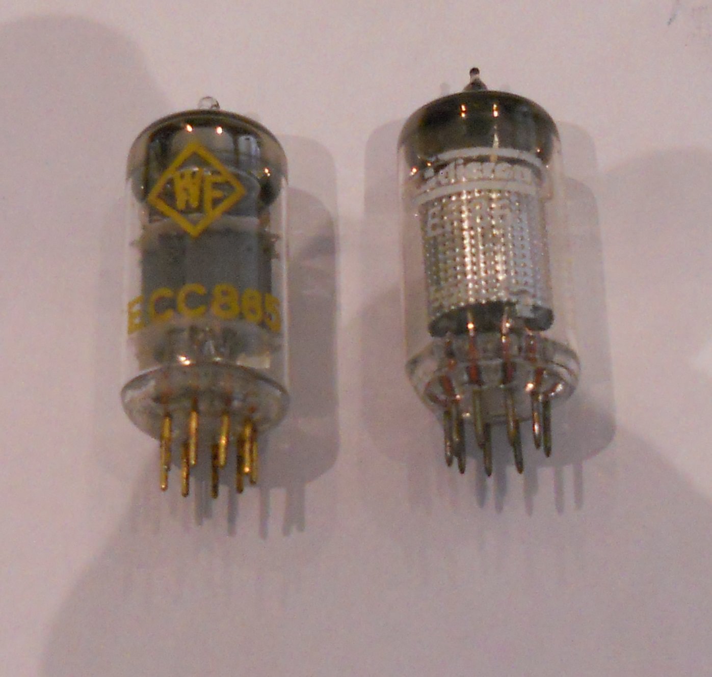
The reason I like the V241 is the output stage. It uses both sections of the ECC85 paired, this maintains the mu at 50, whilst halving the rp. The very low rp allows the use of a simple 150H choke that is still available today. The west German V series amps needed 400 to 700H chokes because the rp of the EF804 is so much higher.
As you noticed, the feedback of the original circuit was complicated because they needed to put caps on the feedback resistors. This type of modification is sometimes required to control instability as it cuts the response over 20 to 30kHz as you have said. Its unlikely that only one person made the V241, so slight differences in wiring from other technicians may have changed the capacitances in the layout and made these mods necessary, I know that Fender did much the same.
DaveP
The original schematic suffered from hum, so they added a small amount to the feedback circuit to cancel it.How about the R23, R24, R25 in the original Schematics??, what will be the reason for are there??.....you don't use them, why?
DaveP said:The original schematic suffered from hum, so they added a small amount to the feedback circuit to cancel it.
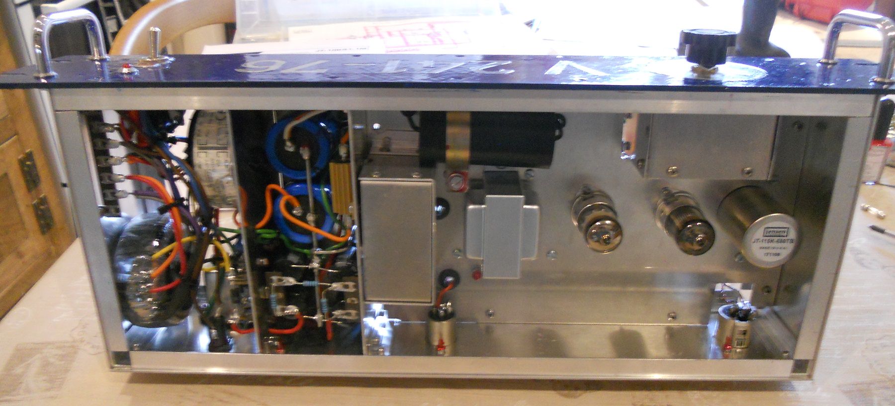
I use toroidal transformers and DC heating for the tubes so there will be less hum than the original circuit.
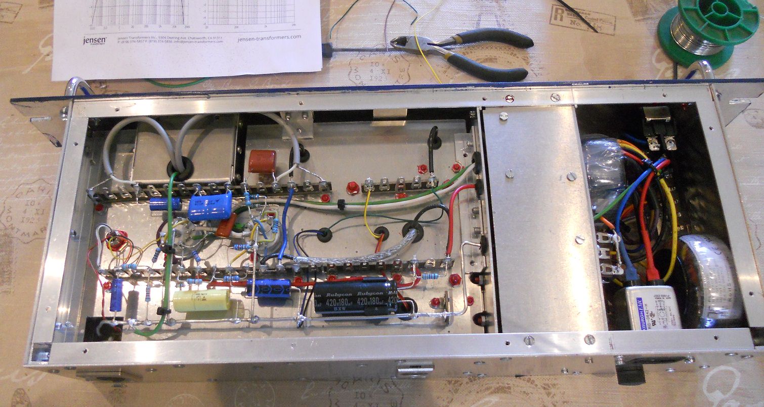
The original V241 was built as a compact box (probably to save space on the desk) my version is built for rack mounting so it gives me more space to separate the power supply from the input signal.
DaveP

The short answer is that it might, but it might not have the same bass response.Wouldn't an ecc81 be OK as a replacement for the ecc85?
") Plenty of sources on the internet for a primer.
Plenty of sources on the internet for a primer.Yes but this formula does not take into account regulation.After the diode bridge on the plate you have 355VDC. Using the diode bridge formula (Vac = Vdc x 0.71) Gives me ~250VAC. This correct?
This is another example of the principle described above. For tube heater supplies, it's better to use two diodes centre-tapped so you only have to worry about two diode drops instead of four with a bridge. The heater TX is over rated so that I get more than 12V with series connection, say 12.6V x 0.71 = 8.95V.Also, for the DC filament section...Are you using 6VAC through the full wave diode config?
DaveP said:A 25W Al clad gets the job done. For some reason 25W types are cheaper than 10 or 15W types.
DaveP
The earth/ground at the IEC socket goes direct to chassis as is the regulation I believe. The amp earth bussbar is only connected to chassis at the input socket (Merlin's design). The amp earth does not touch the chassis anywhere else.You are only connecting to the chassis at the input XLR?
I had gotten the ground scheme from looking at the schematic. In most schematics, including this one, the ground attachment point is at the base of the input transformer (v241, v76, BA2)DaveP said:The earth/ground at the IEC socket goes direct to chassis as is the regulation I believe. The amp earth bussbar is only connected to chassis at the input socket (Merlin's design). The amp earth does not touch the chassis anywhere else.
This is what you are looking for.Is Merlin Blencowe who you are referring to? Is this the book?


![Soldering Iron Kit, 120W LED Digital Advanced Solder Iron Soldering Gun kit, 110V Welding Tools, Smart Temperature Control [356℉-932℉], Extra 5pcs Tips, Auto Sleep, Temp Calibration, Orange](https://m.media-amazon.com/images/I/51sFKu9SdeL._SL500_.jpg)


