V-241 from scratch

GroupDIY Audio Forum

Help Support GroupDIY Audio Forum:

This site may earn a commission from merchant affiliate links, including eBay, Amazon, and others.
While I was testing the S/N ratio, I noticed there was a very low level (-83dB) oscillation at 167kHz.

Any ideas?

I wondered whether I need to up the grid stopper values on the ECC85?

I'll investigate further tonight.

DaveP
 
You can get oscillation due to the wire routing to the gain switch. The grey wires are right next to each other and you might be getting capacitive coupling between them?
I would experiment with the cable layout before trying to kill it with circuit mods. Spread out those grey wires, move some wires around with a chopstick. Particularly the yellow wire from the jensen to the grid.
In my V76 the circuit was behaving really well in my rough rat's nest implementation - then I put in shielded wire, zip tied the cables nicely, and went back to the test bench and I had nasty oscillations. I had tied the cable shields together on the runs to the gain switch and evidently the shield was causing coupling across it. I separated out the shields and it went back to behaving again.

 
@dmp

Thanks for that, I have heard of that problem before with a V76.  Wire dress is critical.

To put it technically, I have 180 degrees of phase shift at or around 167kHz.

I have also found out that the gain is double what it should be, so I will reduce that and hopefully the excessive gain at high frequency will reduce and stop the oscillation.

DaveP
 
I managed to find the source of the problem.

Firstly, because the Jensen OPT had a different ratio it increased the gain, error number one.

The Jensen OPT has a wider frequency range so the treble boost parts R9, C6 & C7. are no longer needed, error number two.

I reduced the value of the feedback resistor R14, from 82K to 24K to get the correct gain figures.

With the lower (correct) gain, there is no trace of the high frequency oscillation and the frequency response is now flat from 20Hz to 35kHz..........Result! :)

I followed dmp's advice and covered the OPT and IPT wires with grounded copper foil.  This is self adhesive and is primarily sold for lining the volume and tone control compartments of electric guitars.  I also tied back the grey screened cables as far as possible.  I have also put a 1M resistor across the primary of the Jensen OPT to give it a bit of HF damping.

The output impedance is ~80 ohms.

I cannot see any hum on my scope and the noise is below my ability to measure.

DaveP

uHyR7un.jpg
 
Nicely done.
Going from 84k to 24k increases the negative feedback to cut down the gain. But why do you have much higher gain than the originals?

The original schematic shows
IPT 1:18, +25 dB
OPT 17:1, -24 dB
Whereas you are using the Jensens:
IPT 1:10, +20 dB
OPT 4:1, -12 dB  ( why not wire the OPT as 8:1? )
So you have 7 dB more from the transformers.
If you wire 8:1 on the OPT, -18dB,  you would be just about where the original was. And you could keep the amount of feedback consistent with the original. (right? - maybe I'm wrong)

 
If you wire 8:1 on the OPT, -18dB,  you would be just about where the original was. And you could keep the amount of feedback consistent with the original. (right? - maybe I'm wrong)
No, you are right and I missed that one. ::)
I re-wired the OPT in parallel and then had to change the feedback resistor from 24k to 56k.

This gave me the following gain figures:-
Nominal Gain.    Actual gain.
55dB                        55.0dB
50dB                        49.7dB
40dB                        39.3dB
30dB                        30.0dB
20dB                        19.0dB

I did not bother with the intermediate values as it shows the gains are close enough.

Observation of the noise trace showed that there was still a lot of hash in the 200kHz region, albeit at a very low level.
I wondered if the vhf  capable output tube and the very large output cap were responsible, so I got to work with the copper foil again.
I covered the output cap with copper foil and grounded it. then I covered the connecting wires as well.  (I recalled that the Quad amp caps had to be shielded).  Finally I put a tube shield over the output tube.

With these measures I was left with just random noise which looked like about 1.5mV p-p at 55dB gain.

1.5mV p-p is around 0.53mVrms

This is - 63.3dBu so at 55dB gain, the E.I.N. is -118.3dBu.

This is unweighted so with the appropriate bandwidth restriction I may approach the V 76 noise levels,

Ian will let me know when he gets his hands on it I'm sure.

As an aside:  The polite sharing of ideas on this forum is what makes GroupDIY a cut above the others IMHO.

Best

DaveP
 
Did you calculate the HF cap/resistors in the feedback section? Maybe your 200K is coming from that.  Also maybe putting  a  cap/resistor that rolls off at 50K close as possible to the cathode, so that any HF garbage is reduced. 

BTW, I’m not clear what dmp did. Did you say to lift the shields at one end? Or just keep the feedback lines to and from the tubes farther away?
 
Also maybe putting  a  cap/resistor that rolls off at 50K close as possible to the cathode, so that any HF garbage is reduced.
I will be doing something similar for my next post.

BTW, I’m not clear what dmp did. Did you say to lift the shields at one end? Or just keep the feedback lines to and from the tubes farther away?
Shields are only connected at one end or else you make a ground loop.  dmp said to separate the feedback cables, which I did.
I discovered which parts/wires were sensitive by carefully touching them with my finger, then I acted as an aerial which makes the noise worse.  That is why I covered the output cap  and its wiring in foil.

DaveP
 
This is my final post on the build as it will be shipped to Ian this week.

2zodzkz.jpg


Here is the output cap covered in foil.  Much easier to do before the build!!!

2331q1.jpg


The direct current feedback from grid to grid is via series connected 390k and 620k resistors.  The 620k is bypassed by a 3pF cap to start dropping off the VHF reponse, about -3dB at 85kHz.  marked with red arrow.

The gain switch cables have been shortened and separated.

2nqvg2u.jpg


Since the OPT was rewired for parallel operation, the output impedance has fallen to a very low 28 ohms at 10Vrms output.
It also gives a very nice square wave performance with minimal overshoot.

Finally, the top cover has been drilled over the tubes to give a little ventilation.

Thanks for watching, Ian at Ruffrecords will be next to comment when he tests it on the bench, then it will be going to my friend Ian Barter for appraisal of its sound.  https://www.ianbarter.com/

Best
DaveP
 
DaveP said:
No, you are right and I missed that one. ::)
I re-wired the OPT in parallel and then had to change the feedback resistor from 24k to 56k.
Looks good - that will make the output tube happier as well.

Interesting that you had to wrap the output capacitor. It might be you could have flipped the orientation of that cap and it would have been better? Some caps show this behavior based on how they are constructed.
Be very careful that the capacitor leads are insulated completely so the copper foil cannot short them out, since the foil is conductive. 

Since the OPT was rewired for parallel operation, the output impedance has fallen to a very low 28 ohms at 10Vrms output.
It also gives a very nice square wave performance with minimal overshoot.
How did you measure the output impedance?
 
DaveP said:
No, you are right and I missed that one. ::)
I re-wired the OPT in parallel and then had to change the feedback resistor from 24k to 56k.

This gave me the following gain figures:-
Nominal Gain.    Actual gain.
55dB                        55.0dB
50dB                        49.7dB
40dB                        39.3dB
30dB                        30.0dB
20dB                        19.0dB

I did not bother with the intermediate values as it shows the gains are close enough.

Observation of the noise trace showed that there was still a lot of hash in the 200kHz region, albeit at a very low level.
I wondered if the vhf  capable output tube and the very large output cap were responsible, so I got to work with the copper foil again.
I covered the output cap with copper foil and grounded it. then I covered the connecting wires as well.  (I recalled that the Quad amp caps had to be shielded).  Finally I put a tube shield over the output tube.

With these measures I was left with just random noise which looked like about 1.5mV p-p at 55dB gain.

1.5mV p-p is around 0.53mVrms

This is - 63.3dBu so at 55dB gain, the E.I.N. is -118.3dBu.

This is unweighted so with the appropriate bandwidth restriction I may approach the V 76 noise levels,

Ian will let me know when he gets his hands on it I'm sure.

As an aside:  The polite sharing of ideas on this forum is what makes GroupDIY a cut above the others IMHO.

Best

DaveP

DaveP,

Sorry for my ignorance but what the E.I.N. means??.....
Opacheco.
 
Interesting that you had to wrap the output capacitor. It might be you could have flipped the orientation of that cap and it would have been better? Some caps show this behavior based on how they are constructed.
Be very careful that the capacitor leads are insulated completely so the copper foil cannot short them out, since the foil is conductive. 
I made sure that the outside foil of the cap was to the plate, according to Aiken.
http://www.aikenamps.com/index.php/where-to-connect-the-outside-foil-on-capacitors.  It's OK the foil does not touch any conducting parts.

How did you measure the output impedance?
I use this method, but there are others:-

Zout = Rtest (Vout - VRtest)/VRtest

With 10.00V output across a 10k resistor, I added a 4.670k resistor in parallel, the voltage dropped to 9.94V

So 10.00 - 9.94=0.06

4670 x 0.06/9.94=28

@opacheco

E.I.N. stands for Equivalent Input Noise at the input.  I used the US standard of a 150 ohm resistor across the input for this test.

https://rupertneve.com/company/notes/impedance-and-noise/

The amp is now packed and ready for the post tomorrow.

DaveP

 
DaveP said:
@opacheco

E.I.N. stands for Equivalent Input Noise at the input.  I used the US standard of a 150 ohm resistor across the input for this test.

https://rupertneve.com/company/notes/impedance-and-noise/.......

Ok thanks DaveP

Opacheco
 
Ian has now tested the mic-pre and these are his results:-

Day 1
The mic pre turned up this morning. I have just finished giving it a quick run through. The performance looks very good so far. I have not made any accurate measurements but I can tell you that:

1. EIN looks to be well below -120dBu
2. Distortion is well below 1% at over +20dBu into a 600 ohms load at 1KHz.
3. Frequency response looks flat out past 40KHz (which is as far as I can measure right now)
4. There is a peak of just under 8dB at just below 7Hz at maximum gain. This is either the resonance of the output capacitor with the primary inductance of the output transformer or the an effect of negative feedback. I have not tried it at other gains.

Day 2
Tonight I managed to carry out a few more accurate tests using my Lindos test set. It produces very accurate signal levels so first I used it to test the actual gain at each gain setting by setting the Lindos output to minus the gain in dBu so the output should always be 0dBu. The Lindos has an input impedance of 20K so these are unloaded gains. The gain error at each gain setting was as follows:

55dB  +0.31dB

50dB  +0.01dB

45dB  -0.23dB

40dB  -0.45dB

35dB  -0.26dB

30dB  -0.25dB

25dB  -0.14dB

20dB  -0.74dB

I then measured the noise at each gain setting. These a quasi peak readings using the C weighting network. The input was shorted. The results were:

Gain        Noise

20dB        -87dBu

30dB        -85dBu

40dB        -81dBu

45dB        -77dBu

50dB        -72dBu

55dB      -67dBu

This represents an EIN of -122dBu which, with this weighting network, is a very good result.
Lastly I measured the 1KHz distortion into a 600 ohm load at various levels. These were all done at 20dB gain. The results were:

Level        Distortion

  0dBu      0.075%

+5dBu      0.049%

+10dBu    0.048%

+15dBu    0.40%

+20dBu    0.64%

+25dBu    1.04%

Again these are very respectable results.

Right now it is not clear if the cause of the LF peak is an output transformer and coupling capacitor resonance or a NFB artefact. Because your design alters open loop gain with closed loop gain, the amount of NFB does not vary much so the size of the peak would probably be independent of gain setting. In a more conventional design where open loop gain is fixed, you would be able to see the peak alter with gain setting if it was due to NFB.

The output cap and the transformer primary form a series resonant circuit which is damped by the transformer primary dcr so to increase damping you would need to add series R not a parallel one. But this would increase the output impedance and reduce the drive capability of the amp which you probably do not want to do.

Day 3.
I have repaired my test interface box and conducted some detailed frequency response and noise tests using REW. First, here is a screen showing the low frequency response at 20dB gain:
1feow5.jpg


As you can see, the peak appears to be at about 11Hz and is about 9dB high. Yesterday when I measured it I got a frequency of about half this and and amplitude of 7dB but I am fairly sure this was due to the faulty switch in my test interface box. I repeated the test at 40dB gain with the same result which unfortunately does not tell us a lot. What I will do is repeat the test with the output loaded with 10K rather than 600 ohms to determine if the effect is load related.

I then switched the sampling rate to 96KHz and looked at the high frequency response:
os5r2a.jpg


As you can see, it is flat out to beyond 40KHz. The sudden drop you can see is the solely due to the sample rate being reached; it is not the response of the amplifer.

Lastly I measured the noise noise spectrum at 55dB gain into a 600 ohm load with the input shorted (I did later check with a 150 ohm input source but the value was unchanged as is typical for tube mic pres):
b3ltag.jpg


The first thing to note is that 0dBFs is +10dBu so you need to add 10dB to the figures in the graph. This means the 50Hz mains frequency and its harmonics at 150Hz and 250Hz are below -90dBu at this gain which is an excellent result. If you look at the top right bubble you will see the rms noise is -80dBFS which is -70dBu. Since we know the gain is 55dB, this gives an EIN of -125dBu which is very good. If you want to play salesman you could always quote the A weighted figure, which is also shown, at -86.7dBFS which is -76.7dBu which gives an A weighted EIN of -131.7dBu.

I have now checked the frequency response into a 22K load and the low frequency response is unchanged so it cannot be anything load related. However, I did notice that there is now an HF peak that was not there when loaded with 600 ohms. The peak occurs around 25KHz (see attached graph). You may need to consider fitting a Zobel network.
141vc4o.jpg


The V241-76 has now been shipped to a studio for sound evaluation.  In the meantime I will make some tests to sort out the 11Hz peak, but as there are unlikely to be many recorded sounds that low, (or as high as 25kHz)  I decided to let the sound test begin as it is.  The square wave performance is very good, but unfortunately, this often goes hand in hand with peaks in the ultrasonic.  The Jensen IPT is not terminated.

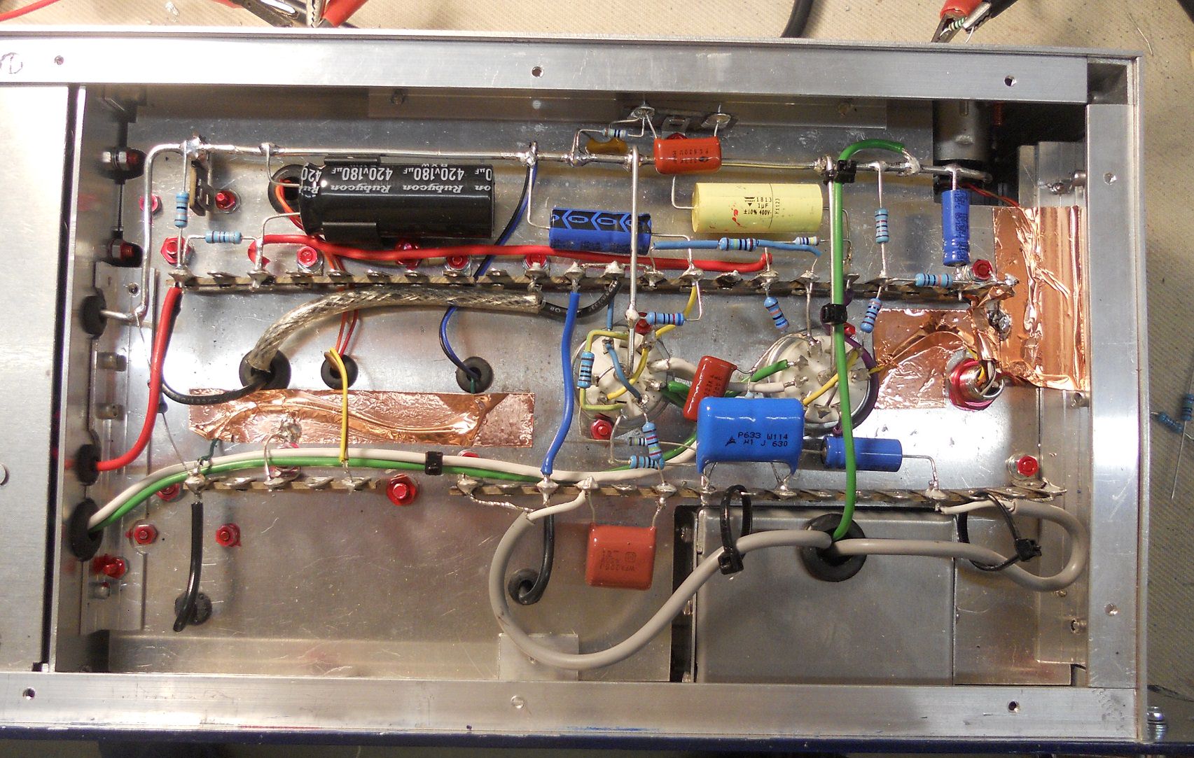
What pleases me most is the very low noise figure.  All that MuMetal and copper screening has played a significant part in that.
It also just goes to show that an ordinary Edicron EF86 pentode can do the business, given the right circuit.

DaveP
 
Interesting results. I built your circuit the last few days and have similar results.
Input transformer is a sennheiser tmb 103 with a 1:15 ratio, shielded. Output transformer is a oliver archut 6,5:1 (BV308)  microphone transformer I had lying around. I tried it for testing purposes, If that preamp turns out to be good I will replace it probably with something larger and shielded. But even right now the amp sounds very, very good. But maximum level at 50Hz is only around 2dBu. After that distortion explodes. But since I record at sane levels, this could be enough, I will try a little longer.
Mine has  worse hum levels though due to a smaller enclosure resulting in a compromised layout and no shielded output transformer.
Here is a measurement with a rme sound card at 55dB gain, input terminated with 150 ohm.
0dB fs is at +19 dBu.
The RMS noise figure  seems to be good though:
1ilh5j.jpg


The low frequency bump is there, too, but less pronounced:
5ajiau.jpg

could that be the result of some HiPass filtering in the feedback loop? Should we try a larger blocking cap than 2.,2 uF?

More testing and fine tuning will follow, but right now it sounds great and my hum levels are ok in real world recording situations. Wouldn't use it with ribbons recording a string ensemble, but recording acoustic guitar with a condenser at 40dB gain is totally fine.
Thanks Dave for that idea with the v76 front end.
Edit:
OK, I performed a few experiments  with the LF peaking. Changing the value of C9 changes the amplitude and the frequency of the peak, the larger the cap, the less peaking I get. I would probably need something like 25uF to cure it.
Strange thing for me  is, that the peak amplitude and frequency changes with the level of the signal.  But not with the amount of feedback. With 10dBu I get a peak at around 20HZ +6dB, at 0dBu around 10 HZ +4dB  and with -20dBU the peak is not measurable any more for me and the signal is pretty much flat.
Why is that?
One question I have:
What is the purpose of R4 and C6?
I left them out of the circuit and I could not measure any difference.
Thanks Tobias


OK, I performed a few experiments  with the LF peaking. Changing the value of C9 changes the amplitude and the frequency of the peak, the larger the cap, the less peaking I get. I would probably need something like 25uF to cure it.
Thank you Hop.sing
I tried to stick with the V76 schematic as far as possible, so that's why I used the 2.2uF.  Now I realise that 2.2uF would be fine for the high output impedance of an EF86 tube and choke, but the output impedance of the ECC85 is so much lower and probably needs a larger feedback cap.

One question I have:  What is the purpose of R6 and C4?
I left them out of the circuit and I could not measure any difference.

The short answer is, I have no idea!  It could be that they cured an anomaly with the original transformers or layout in the  V 241.
The -3dB point of a 3 Meg resistor and 100nF cap is 0.53Hz,  I left them in, in case they were essential to correct the DC feedback or coupling between the tubes.  I intend to make another at some point so I will do some more work on the issue then.

DaveP


I tried to stick with the V76 schematic as far as possible, so that's why I used the 2.2uF.  Now I realise that 2.2uF would be fine for the high output impedance of an EF86 tube and choke, but the output impedance of the ECC85 is so much lower and probably needs a larger feedback cap.
I did not play with C8 (2.2uF) yet, just the large coupling cap C9.
Looking at the frequency graph I think there is some interaction from capacitance and inductance. I will try C8 next.
 
Working back from the LC resonance formula and 11Hz, I get a primary Inductance on the Jensen OPT of 20.93 Henries, which is just about the level I would expect.  A 25uF cap would only push the resonant frequency down to 7Hz.

Maybe some resonance damping or bass cut might be a better approach.  Hmmm............. :-\

DaveP
 

Latest posts

Back
Top