Echo North
Well-known member
Hi,
This site has a great list of UREI schematics:
http://www.waltzingbear.com/Schematics/Urei.html
What we are looking at is the "Urei 1176LN series F, "Black face", push pull class AB output". Particularity the input circuitry located on page one:
http://www.waltzingbear.com/Schematics/Urei/Urei_1176LN_series_F_page_1.htm
I believe adding the "T" attenuator with the UTC O-12 clone is a great addition to this project, making it more like a true revision F.
I sell a T attenuator here:
http://hairballaudio.com/shop/product_info.php?cPath=21&products_id=33
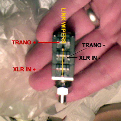
Since this is the 3-deck non bridged pot that Purple uses, the wiring is a little different then on the schematic. For wiring instructions you can have a look at the Purple schematic or just see Matt's picture:

The C-3837-1 connections are (not confirmed... please check my work):
Pin 2 (- from T attenuator)
Pin 4 (+ from T attenuator)
Pin 5 ( + to board)
Pin 6 (ground)
Pin 8 (- board)
Check the F input circuit. I'm guessing you'll want to connect the + to pad 2 of the "input gain" and the - to pad 3 with a 270ohm resistor in parallel.
Not a pro here and I'm taking a stab at this by looking at schematics quickly, so for the love of god someone check my work!
Mike
This site has a great list of UREI schematics:
http://www.waltzingbear.com/Schematics/Urei.html
What we are looking at is the "Urei 1176LN series F, "Black face", push pull class AB output". Particularity the input circuitry located on page one:
http://www.waltzingbear.com/Schematics/Urei/Urei_1176LN_series_F_page_1.htm
I believe adding the "T" attenuator with the UTC O-12 clone is a great addition to this project, making it more like a true revision F.
I sell a T attenuator here:
http://hairballaudio.com/shop/product_info.php?cPath=21&products_id=33
Since this is the 3-deck non bridged pot that Purple uses, the wiring is a little different then on the schematic. For wiring instructions you can have a look at the Purple schematic or just see Matt's picture:

The C-3837-1 connections are (not confirmed... please check my work):
Pin 2 (- from T attenuator)
Pin 4 (+ from T attenuator)
Pin 5 ( + to board)
Pin 6 (ground)
Pin 8 (- board)
Check the F input circuit. I'm guessing you'll want to connect the + to pad 2 of the "input gain" and the - to pad 3 with a 270ohm resistor in parallel.
Not a pro here and I'm taking a stab at this by looking at schematics quickly, so for the love of god someone check my work!
Mike


![Soldering Iron Kit, 120W LED Digital Advanced Solder Iron Soldering Gun kit, 110V Welding Tools, Smart Temperature Control [356℉-932℉], Extra 5pcs Tips, Auto Sleep, Temp Calibration, Orange](https://m.media-amazon.com/images/I/51sFKu9SdeL._SL500_.jpg)


