All things G1176 - the new "repost" thread.

GroupDIY Audio Forum

Help Support GroupDIY Audio Forum:

This site may earn a commission from merchant affiliate links, including eBay, Amazon, and others.
Zee1usa,
I have gotten to step 1 , but I get no increase or decrease
when I adjust the input control. I have the 250hz/.245 V AC
on input pin 2 and 1 (do i need to jumper pin 1&3?)
As far as I know I got my pots and XLR's wired correct.
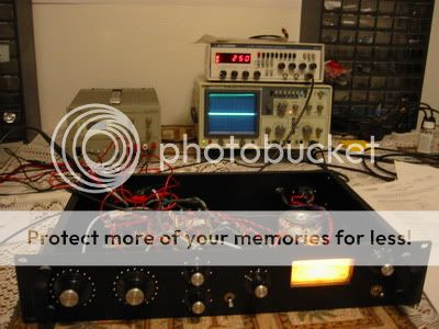
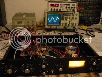
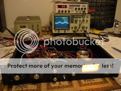
Pin 1 is wired to ground permanently(0V).
Pin 2 carries the positive swing of the input signal (+).
Pin 3 carries the negative swing of the input signal (-).

If your signal generator's output is balanced, it should be connected as described above.

If your signal generator's output is unbalanced, connect pin 3 to pin 1(ground), and apply signal to pin 2, using pins 1 or 3 as ground.

Basically, if you want to connect unbalanced gear, you need to connect the low side of the balanced connection (-), (pin 3) to ground (0V), (pin 1). That makes your balanced input or output unbalanced.

You should have roughly unity gain up to the high side of the input pot.

If your question was about something else, or I misunderstood you, please say so.

Orson, did you get the buzz to go away? It sounds like it wasn't even coming from the PCB...

Dean
 
Hey Dean :thumb:

Thanks for asking. Well three things were happening. Two were buzzes with oscilation and one is a hum. The external sound card (emagic emi 2/6 USBsound card) was creating a problem. So I have three sound cards to choose from. I switched to another one and the one buzz was gone. then I wiggled the power chord connected to the IEC and the other higher pitched buzz went away but comes back now and then and then I wiggle it again and it goes away. But the Hum, well its still there. it's low frequency and low volume, but you know me, i want perfection. It gets the loudest when the ouput pot is turned all teh way down ( full CCW) The hum gets the softest when the output pot is turned to around 12 o'clock. I have shielded cable in the unit, I have the torodial transformer far away from the audio trannys, I have short jumper wire under the pcb ( for the Chef mod.) I have a thick wire soldered around the ground trace connected to star ground. At this point, I don't know what to do. Jakob in a PM told me to try different grounding schemes. I'm game but as usual have no education to refer to with these things. Other than that I took it to a gig and it worked great. I did some Bee-Gee covers and it really helped get that falseto vobrato thing going real nice. I love playing with vocal volume wiht this compressor! Despite the Hum, this thing rocks!
 
Hum, well its still there. it's low frequency and low volume, but you know me, i want perfection. It gets the loudest when the ouput pot is turned all teh way down ( full CCW) The hum gets the softest when the output pot is turned to around 12 o'clock
Yeah, that is the one related to the grounding scheme. Just for kicks, put the thick wire you added around the PCB and the IEC ground wire to the single grounding point at the chassis; nothing else. All the other grounds should just go to their respective points on the PCB.

Are you floating the sheild at one end on your pot runs?
I have short jumper wire under the pcb ( for the Chef mod.)
Based on your gain readings, you don't have this mod(Chef mod=1:1); you have the 1:2 mod(better in my opinion because it's closer to the original specs). That is unless you changed something since we made all those gain measurements.

Good luck,

Dean
 
[quote author="deanp920"] Yeah, that is the one related to the grounding scheme. Just for kicks, put the thick wire you added around the PCB and the IEC ground wire to the single grounding point at the chassis; nothing else. All the other grounds should just go to their respective points on the PCB. [/quote] Will do. i'll let you know the results.

[quote author="deanp920"] Are you floating the sheild at one end on your pot runs?[/quote]

Oh, there you go speaking Japanese again :p No, I am not a police officer busting drug rings and if I was I wouldn't make my police badge obvious by floating it around for people to see! Ok, now tell me what you asked me means. :?


[quote author="deanp920"] Based on your gain readings, you don't have this mod(Chef mod=1:1); you have the 1:2 mod(better in my opinion because it's closer to the original specs). That is unless you changed something since we made all those gain measurements.[/quote] My apologies, you are correct. I don't have the Chef mod :roll:
 
deanp920 wrote:
Are you floating the sheild at one end on your pot runs?


Oh, there you go speaking Japanese again :p No, I am not a police officer busting drug rings and if I was I wouldn't make my police badge obvious by floating it around for people to see! Ok, now tell me what you asked me means.
:green: Well, it's probably not a big concern, but the best way to run from, say, the PCB to the input potentiometer would be to use a cable with 3 conductors plus a sheild; the sheild would then be connected to the same pad on the PCB as the potentiometer's ground wire, while at the other end of the cable the sheild would not be connected to anything.

But lots of folks use 2 conductor cable plus a sheild, and with this arrangement one must use the sheild as the ground conductor as well, connecting it at both ends of the cable run. Now the sheild has a little bit of current flowing through it; something that might contribute to ground loop-induced hum. I suppose you could run a separate ground conductor alongside the 2 conductor sheilded cable so you could float the pot end of the sheild as in the first scenario.

Dean
 
Hello Dean (and Jakob),

The signal gen input is now balanced.

FYI: I have done your output transfo mod (cut 4 traces and jumped 4 wires)

I tried the UREI manual procedure for calibration of Q bias.
Inject a 1K signal at 0db/.775 (i was able to get .765 out of my sig gen)
input= full ccw
output= full cw
attack= full ccw
release= full cw
ratio= 20:1
meter=VU or 4+db
Q bias= full ccw


when i adjust the input gain I get no response on the VU even if I try adjusting the Q bias pot as well ..nothing!
This is my first task, to get past this point. I was thinking that this
is the procedure I should follow because I have done the mod you suggested on the output transfo?

I have also tried the calibration for Q bias that Kdawg posted.

Here is Kdawgs procedure:

Q Bias
Release: Fully CW (Fast)
Attack: Fully CW (Fast)
Input: Fully CCW (off)
Output: Fully CW
Ratio: 1:4
Meter: Bypass
Q bias: fully CCW

Signal Generator: 0.245 V (AC) sine wave 250 Hz
Measuring across input pins 2 and 1 & 3 for ground

1. Turn up input control until I get 0.100 V AC, measuring across output pins 2 and 1 & 3 for ground

2. Rotate Q Bias until reduced to 0.089 V AC across output. [ 1 dB = 20 log (0.100 / 0.089) ]


But I am not sure if i should follow his
procedeure because I think he did the chef output mod
and I have done your mod (not chef's)?

anyways.. I tried Kdawg's procedure and I got some output
but while tweaking the input/output knobs. Not sure If this
is a good step in the right direction, but here are some pics:

settings adjusted per Kdawg calibration "Q" bias
scope is flat or 0 volts.

1.jpg


Output gain up a 1/4 turn and getting some output signal
4Vpp (probe on x10) Input gain is still at full CCW

2.jpg


Output gain up 1/2 way starting to clip about 5vpp (x10 probe)
Input gain is still at full CCW

3.jpg


Output and input at 1/2 way up. 5vpp approx. (scope on 10x)

4.jpg


Both input and output at full CCW 5Vpp

5.jpg


Input and Output 1/4 way up. 2Vpp

6.jpg


Hope these pics may help somewhat in going forward on
calibrating this thing?


Checked the BF 245A fet and the G-S-D are stuffed proper.

All voltages on transistor E-B-C seem to be ok ..as posted above.

XLR's and potentiometers are wired properly and all else as well.

All component values are correct and stuffed properly.


Thank you for any help you can offer/advise

:?
nick
 
Remember you won't get any meter display on bypass mode... only on GR or VU. The output procedure works fine with any output mod as far as I know, since the metering is connected on the output of the transformer.

Are you measuring voltage visually on the scope, or using a DMM to get the value? I used the DMM on the input, then switched it to output.

-kdawg
 
Thanks for the quick reply Kdawg!

[quote author="kdawg"]Remember you won't get any meter display on bypass mode... only on GR or VU. The output procedure works fine with any output mod as far as I know, since the metering is connected on the output of the transformer.

Are you measuring voltage visually on the scope, or using a DMM to get the value? I used the DMM on the input, then switched it to output.

-kdawg[/quote]

Hello Kdawg,

I have 250hz and .245 measured on my DMM (true rms)
all knobs tweaked per your procedure.

I have tried to follow your procedure exactly and am not getting
any voltage at all on the output ..none (on the DMM)
while turning the input gain from the full ccw position slowly towards the cw position . :oops:

I do realize the The meter only works in "GR" and "VU"
and not bypass. I only was looking at the VU while trying the UREI
procedure and not yours =}

:? I will keep scratching my head.
 
Zee1usa,

Let's back up a little and try to get on the same page here. Please bear with me.


Use a 50mV, 250Hz input signal. Measure with your DMM for now and hold off on the scope(perhaps use it to look for clipping only right now). This way we can compare AC readings in RMS.

With this input signal, put the input and output at max(full CW). Ratio = 20:1. Attack and release don't matter, just set them like the manual says. Unit in bypass. Measure across input XLR pins 2 and 1&3. You should have ~50mV.

Measure from the input potentiometer wiper to ground. You should have ~50mV(a little less if you have the transformer input...I'm losing about 15mV, or 3db through the input transformer). So, 50mV at the input wiper with the IC input, or 35mV at the input wiper with the transformer input.

At this point, I would hop over to output XLR pins 2&3 and measure across them with the DMM. Turn the Qbias pot full one way or the other until you have max signal. You should have about 4.8V with no clipping(~6.8 with the IC input). Back off the Qbias trimmer until you have about 4.3V(~6V with the IC input) and that should set the Qbias fairly close. You just want Q1 to start cutting off a little bit, that's all we're doing here.

See if you can get this far, and if not let us know where things fell apart.

Dean
 
[quote author="deanp920"]Zee1usa,

Let's back up a little and try to get on the same page here. Please bear with me.


Use a 50mV, 250Hz input signal. Measure with your DMM for now and hold off on the scope(perhaps use it to look for clipping only right now). This way we can compare AC readings in RMS.

With this input signal, put the input and output at max(full CW). Ratio = 20:1. Attack and release don't matter, just set them like the manual says. Unit in bypass. Measure across input XLR pins 2 and 1&3. You should have ~50mV.

Measure from the input potentiometer wiper to ground. You should have ~50mV(a little less if you have the transformer input...I'm losing about 15mV, or 3db through the input transformer). So, 50mV at the input wiper with the IC input, or 35mV at the input wiper with the transformer input.

At this point, I would hop over to output XLR pins 2&3 and measure across them with the DMM. Turn the Qbias pot full one way or the other until you have max signal. You should have about 4.8V with no clipping(~6.8 with the IC input). Back off the Qbias trimmer until you have about 4.3V(~6V with the IC input) and that should set the Qbias fairly close. You just want Q1 to start cutting off a little bit, that's all we're doing here.

See if you can get this far, and if not let us know where things fell apart.

Dean[/quote]


Hello Dean,

Thanks for the help!

ok, I am using a 250hz 70mv signal because that is the lowest this
signal generator will do. so I inject this signal into the input
measure the ground and wiper on the input pot and I get
51mv and this is what I am expecting there considering I am using the input transfo, so were off to a good start (baby steps :grin: )

Next, I measure the output XLR between pin2 and 1/3
with input and output potentiometers full CW.

But if I adjust input and output potentiometers full CCW
I am getting 6.95VAC true rms. "Q" Bias pot
does not seem to do anything.

Thanks for the advise it is very much appreciated!

Nick


NWSM:

tonight sounds good!
 
Docta Dean,

Well I did as you recomended and the hum got a little worse :green:. No problem though this just proves that it's definately a ground hum.

I have my star ground as one of the bolts that holds the IEC to the chasis. I am wondering if this is a bad thing because the Toroidal transformer is between 2 and 3 inches away from it. Perhaps I should create a new star ground closer to the xlr's which is farther away from the toroidal tranny?
 
Hello dean,

Here is an update. It appears that I am getting proper voltage signal
on the output XLR, but the "Q" Bias potentiometer has no effect at all.

I measured the Q1 fet/transistor. I am getting:

Q1
G = -1.92v
S = 0v
D = 0v


I think there is an issue here. There is alot of stuff tied to this.
I will keep looking. Any questions you may ask to clue me in
would be more than welcome.

Thank you Dean!

:?
Nick
 
Nick,

Ok, I get about -1.8V at the gate of Q1 with my bias set for 1db cutoff. I can adjust this from -2.3V to 0V with the Qbias trimmer.

The less negative this voltage becomes, the more Q1 goes low and attenuates the audio. Actually, there is a fairly abrupt point where Q1 begins to clamp down. We set the bias just slightly inside this spot.

May I assume that this voltage does not change when you turn the Qbias trimpot?

If so, go back to the schematic and PCB overlay and trace through the Qbias supply circuit, starting at the -10V PSU then proceding through the Qbias trimpot to find out why you can't adjust the bias voltage on Q1.

Perhaps I'm making a hasty assumption. Let me know how it's going.

Orson,
I have my star ground as one of the bolts that holds the IEC to the chasis. I am wondering if this is a bad thing because the Toroidal transformer is between 2 and 3 inches away from it. Perhaps I should create a new star ground closer to the xlr's which is farther away from the toroidal tranny?
Well, it is hard to say; I have my star point set at the mounting screw for the input XLR. This is the spot called for by Jakob. Make damn sure you clean this spot to bright metal to ensure a SOLID electrical connection. When it comes to grounding, think BEEFY. Think BLACK HOLE for electrons. Make sure the panels comprising the chassis are making solid electrical connection with each other. Play with it to see if you can make an improvement and if you can't go back to what you had originally. Sometimes I'll use a length of heavy, tinned buss wire that I'll solder between various 0V, or ground, locations to try and get some clues about what helps. Don't waste time with clip leads; those will drive you crazy.

Try using the input XLR screw as star ground first. Put the heavy buss wire off the PCB here and the IEC ground here.

Hope that helps.

Dean
 
Hi Dean,

[quote author="deanp920"]Nick,

Ok, I get about -1.8V at the gate of Q1 with my bias set for 1db cutoff. I can adjust this from -2.3V to 0V with the Qbias trimmer.

The less negative this voltage becomes, the more Q1 goes low and attenuates the audio. Actually, there is a fairly abrupt point where Q1 begins to clamp down. We set the bias just slightly inside this spot.

May I assume that this voltage does not change when you turn the Qbias trimpot?

If so, go back to the schematic and PCB overlay and trace through the Qbias supply circuit, starting at the -10V PSU then proceding through the Qbias trimpot to find out why you can't adjust the bias voltage on Q1.

Perhaps I'm making a hasty assumption. Let me know how it's going.


Dean[/quote]


My Q Bias trimmer is adjusting this voltage.

But I am not getting any change at the base of Q2.

I was speaking with NWSM, and we are thinking something may be wrong with Q1?

On initial power up FYI I had wire (17) and wire (15) swapped
then I noticed this shortly after and corrected this.

Do you think this could of done damage to Q1 or related transistors?

I'll keep looking, but it may be narrowed down...

Thank you Dean!

:thumb:

zee
 
Hey Dean,

Good news! :grin:

I was chatting on the phone with NWSM/KIRK and we talking about Q1
possibly being bad and then he had me probe a few voltages around
Q1 and further downstream. Everything else seemed to be working correctly except Q1 was suspect. NWSM suggested I replace suspected Q1. I did and now I can make this calibration adjustment and move on the the next step. I'm not going to break out the :guinness: yet. :wink:

Thanks dean, your pointing me in the right direction led me to fix this.
and here's one for NWSM :guinness:


One thing I want to ask about the input and output potentiometers.

Mine seem to be backwards, but I did wire pin 1 on the 10k input pot
to pin 1 on the pcb..pin 2..pin 3 respectively.

I thought I remember Jakob mentioning to watch out for this?? :?

Maybe you or jakob could shed some light on this issue?


I hope this is helpful to others.
Thanks

Nick :guinness: :green:
 
Zee,
But I am not getting any change at the base of Q2.
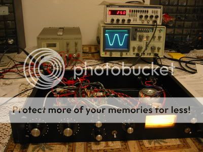
Are you talking about measuring change in AC signal level here?
On initial power up FYI I had wire (17) and wire (15) swapped
then I noticed this shortly after and corrected this.

Do you think this could of done damage to Q1 or related transistors?
I doubt that mistake damaged anything whatsoever.

If, at the turn of the Qbias trimpot, the negative voltage changes from 0V to ~-2V at the gate of Q1, then I would probably try replacing Q1, based on what you've said so far. It's nice to have a socket of some sort for Q1.

Are you using BF245A?

Dean
 
Hello Dean,

Check the previous post, I think we were both typing and you may of posted seconds after I did and not noticed (its a refresh thing)

:wink:

Yes, I am using the "BF245A"
 
Woops! I hit submit before I caught your last post.

Glad swapping Q1 helped you break loose a bit. :grin:
One thing I want to ask about the input and output potentiometers.

Mine seem to be backwards, but I did wire pin 1 on the 10k input pot
to pin 1 on the pcb..pin 2..pin 3 respectively.
It might be your particular potentiometer. At any rate, just make sure you've got the wiper going to the right spot and reverse the other two until it works in the right direction. I like to check my pots ahead of time with an ohmmeter to see exactly what changes CW/CCW rotation causes between the wiper and the other contacts; that, along with the schematic and PCB overlay leaves no doubt about how to connect it.

FWIW, the rotation on my Qbias trimpot is opposite that stated in the UREI manual.

Dean

Dean
 

Latest posts

Back
Top