CJ
Well-known member
Back at it on the winder math. Figured out how to determine the angle that the wire would make with the bobbin as it relates to the distance that the feeder pulley is from the center of the bobbin.
Picking the right frame of reference and coordinate system can sometimes make a terible problem a lot easier. With trig, it's nice to have one or more boundries set up to equal either 0 or 1 if you can do it. Also, before I was going to do the math of the x axis only, negating any y axis motion, thinking that if the wire was far enough away from the bobbin that the effects can be ignored. This turned out to be less than realistic, as the wire will be close enough to the bobbin to feel the effecyts of y axis accelration. So now I am including y movement with the math. Two space is not too difficult, right? :shock:
This problem puts a square bobbin in a round circle, so we will probably be dealing with two coordinate systems. One for circular motion, and one for an X-Y cordinate system.
If you tape the magnet wire to the corner of the bobbin and pull on it, the bobbin will align itself. This alignment will put the corner of the bobbin on the x axis, along with the center of the bobbin, or the spindle of the winding machine, and the feeder pulley. This is how I set up all the problems.
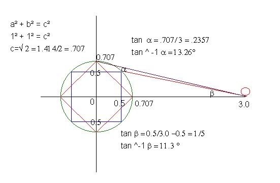
In order to find the angle of the wire, I constructed a line segment perpindicular to the tanget line formed by the wire and the bobbin at the start of the winding cycle. Now, since we have a right triangle, we can solve for the angle by using the length of this perpindicular and the distance between the pulley and the center of the bobbin. For a square bobbin, the wind cycle will form a periodic function in the circular motion cordinate system that repeats itself every 90 degrees. The start of this function will depend on the size of the bobbin and the distance to the pulley. It took quite a while to find this hidden triangle needed to solve the problem. The crux of the solution lies in the fact that the perpindicular line segment pulls the tangent line into the correct frame of reference.
Here is a picture of the solution. You could do an extra step and use the two sides of the triangle to find a third, and then use the arc tangent method: ø = arctan L/√(D^2 - L^2)
Anyway, here is the pic. The triangle used can be transposed into a different quadrant in order to put the angle needed in the normal position. Note that as the bobbin fills up, the angle steepens. (PRR) Also, see that the radius of the circle that a square bobbin and wire travel in will be L x √2 .

You could use implicit differentiation in order to see what happens to the angle as the distance increases, or just look at the graph of an tangent function, or just realize that as you increase the distance to the bobbin, the angle tends rapidily toward zero.
Picking the right frame of reference and coordinate system can sometimes make a terible problem a lot easier. With trig, it's nice to have one or more boundries set up to equal either 0 or 1 if you can do it. Also, before I was going to do the math of the x axis only, negating any y axis motion, thinking that if the wire was far enough away from the bobbin that the effects can be ignored. This turned out to be less than realistic, as the wire will be close enough to the bobbin to feel the effecyts of y axis accelration. So now I am including y movement with the math. Two space is not too difficult, right? :shock:
This problem puts a square bobbin in a round circle, so we will probably be dealing with two coordinate systems. One for circular motion, and one for an X-Y cordinate system.
If you tape the magnet wire to the corner of the bobbin and pull on it, the bobbin will align itself. This alignment will put the corner of the bobbin on the x axis, along with the center of the bobbin, or the spindle of the winding machine, and the feeder pulley. This is how I set up all the problems.
In order to find the angle of the wire, I constructed a line segment perpindicular to the tanget line formed by the wire and the bobbin at the start of the winding cycle. Now, since we have a right triangle, we can solve for the angle by using the length of this perpindicular and the distance between the pulley and the center of the bobbin. For a square bobbin, the wind cycle will form a periodic function in the circular motion cordinate system that repeats itself every 90 degrees. The start of this function will depend on the size of the bobbin and the distance to the pulley. It took quite a while to find this hidden triangle needed to solve the problem. The crux of the solution lies in the fact that the perpindicular line segment pulls the tangent line into the correct frame of reference.
Here is a picture of the solution. You could do an extra step and use the two sides of the triangle to find a third, and then use the arc tangent method: ø = arctan L/√(D^2 - L^2)
Anyway, here is the pic. The triangle used can be transposed into a different quadrant in order to put the angle needed in the normal position. Note that as the bobbin fills up, the angle steepens. (PRR) Also, see that the radius of the circle that a square bobbin and wire travel in will be L x √2 .
You could use implicit differentiation in order to see what happens to the angle as the distance increases, or just look at the graph of an tangent function, or just realize that as you increase the distance to the bobbin, the angle tends rapidily toward zero.