GroupdDIY 511 Racks: round 5.5 available

GroupDIY Audio Forum

Help Support GroupDIY Audio Forum:

This site may earn a commission from merchant affiliate links, including eBay, Amazon, and others.
Time for an update.

Second batch of 100 is under production. Connectors are in stock.

The design of the mechanics of the psu is completed and I am building the final prototype this weekend and will be testing it. It is almost there.

Stay tuned.
 
sahib said:
You have the picture don't you?  ;)
Why yes I do!

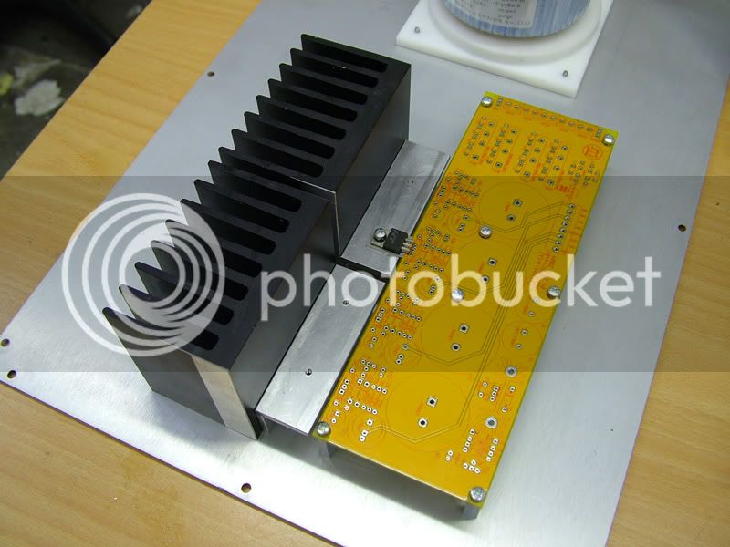
Cemal_psu_proto.jpg


Nothing like a big-ole heat sink!  ;D
 
Ha!!

Kind of ridiculous AND cool at the same time.  Can't wait..  :)

Plus this means I get to sell my API Lunchbox!

Anyone want to buy one?

Thought not...
 
If you meant the size of the heatsink it is not really ridiculous. You have no idea how hot it is down there. I expect the surface temperature on the L bracket to be around 45-50 degrees C under full load. Transformer will also run at around 55 degrees C under full load. This is normal by the way as Volker has already checked it with the manufacturer. However, I made the boss of the acetal mounting plate (white thingy under the transformer) to go under the transformer to create a gap so that it actually hangs over with bottom part of the winding exposed, releasing heat in the air.
 
Sorry, I didn't get it. No probs. Whole aim is to run it as cool as possible within the budget. Obviosuly we can stick a big door stopper there and it won't go beyond 30 degrees but it is unnecessary and costly.

 
Why the L bracket? Is that just to keep the heatsink away from the pcb?

FWIW, I found a large 12x9 heatsink on ebay and quartered it on the bandsaw. My plan was to mount them on the sides of a 2u case.
 
The L bracket is there for ease of assembly and servicing.

The other option can be that you can have a single heatsink but the regulator pairs are seperated by the L bracket. In which case L bracket allows a good seperation between the regulator pairs so that when one pair is working harder and dissipating greater heat, it does not heat up the other regulators unnecessarily.

However, I chose to use seperate heatsinks with a view that both regulator pairs will work under full load. In terms of cost there is a little increase in labour but it is worth in the long run.
 
I have finished the heatsinks for the rectifiers and I am populating the pcb at the moment. I am going home just now and will continue tomorrow. 

rectifiers.jpg
 
sahib said:
I have finished the heatsinks for the rectifiers and I am populating the pcb at the moment. I am going home just now and will continue tomorrow. 

rectifiers.jpg
Oh My Cemal.  :eek: :eek: That is frickin' awesome!! I have been looking around for a stock heat sink but have been striking out for that bridge rectifier package. I am so impressed by what you have done here!!  :)

Best, Jeff
 
sahib said:
Just to keep you happy Jeff, just to keep you happy. 8)
Thanks Cemal! But it's more about those rectifiers. If we keep those 4 hard working guys happy (and cooler)...I in turn I will be happy!
 
Cemal,

It's hard to tell from the picture alone, but isn't the thermal resistance of this combination dominated by the L-profile? This looks like a bit of a waste of a fine (and probably expensive) heatsink. If nothing else, it may be useful to replace the L-profile with a T-profile to improve the thermal coupling.

JDB.
[constructions like this one usually show a strong thermal gradient across the horizontal part of the L-profile, particularly since as shown the die of the regulators is almost at the edge of the profile]
 
Back
Top