kante1603
Well-known member
Line level.mattmartin831 said:Do these work with both mic level signals and line level signals? Or just one or the other?
Line level.mattmartin831 said:Do these work with both mic level signals and line level signals? Or just one or the other?
Hello,dogfaceaudio said:Does anyone have info on dimensions for drilling a front panel? Thanks.
Excactly,and +1 on updating the bom!dmp said:Nice work, Doug.
So a INA137 or THAT1246 on the input gives unity gain (instead of INA134, which is +6dB).
Those 134 chips are expensive - maybe the BOM on the first page could be updated?
Hello,I found this some minutes ago:dogfaceaudio said:Anyone have a source for the 47K Rev. Log pots? Audiomaintenance is out.
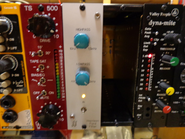
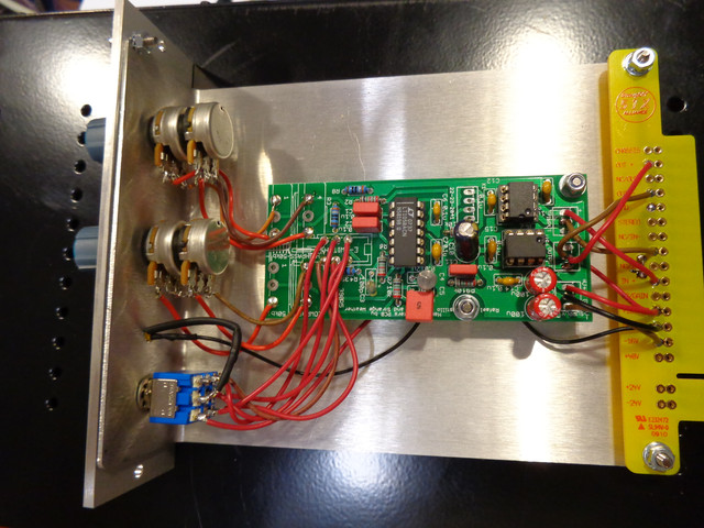
Marcocet said:It looks like 12afael, Jens and I finally have a production version of this PCB ready and we're about to place an order for ourselves. Essentially it's a clone of the classic Harrison sweepable filters. The board runs on +/- 15v, has extremely few parts, and is tiny enough to fit a bunch in a rack case. It could also easily be built into a 500 series module. The hardest parts to source are the 47k Rev Log pots, which are available at Audio Maintenance (thanks Colin!).
I'm not trying to run a shop or anything, but if anybody would like a few boards I can figure out a price and add them in to our order. Please feel free to PM me or email me at strangeweathersound @t gmail.
EDIT:
Boards are sold out. Here's the BOM. I've attached an excel copy too for those who are that way inclined.
5 10k R1, 2, 6, 7, 9
4 390 R3, 4, 5, 8
9 0.1u C1, 2, 6, 7, 11, 12, 13, 15, 16
1 100p C3
1 0.012u C4
1 0.047u C5
2 100u C8, 9 electrolytic
1 10u C10 electrolytic
2 50k Dual Lin LOPASS, HIPASS Audiomaintenance.com
1 ESWITCH 2 pole switch Audiomaintenance.com
1 INA134P IC2
1 TL074P IC1
1 DRV134PA U$1
http://strangeweatherbrooklyn.com/sales/HarrisonFilterBOM.xls
schematic here
Who did you ask?leighgreen said:Hi, could I please buy some of these? I've asked a few times but nobody has answered me.
Thanks!
dandeurloo said:skizotom, Just the input pads have the wrong silk screen on them. If you look at the bottom of the PCB or use your DMM you can see the ground pads are tied together.
Correct wiring is:
INPUT OUTPUT
+ - G G + -
o o o o o o
I hope that helps.


Enter your email address to join: