PLASMA PBG12201 VU KITS-AS PROMISED!

GroupDIY Audio Forum

Help Support GroupDIY Audio Forum:

This site may earn a commission from merchant affiliate links, including eBay, Amazon, and others.
Strange, I checked the voltages with my board, all correct (plus-minus for trimpot positions, etc)....
At this stage we should check with scope if PIC puts out the signals,
but seems, the PIC isn't a problem, I have close voltages..
In any case, pm me your shipping address, and I will send you
another PIC for shipping+pic self cost.

Check transistors MPSA42 have EBC layout. Check all resistors going to PBG display.
Check display itselves( put +240V to anode through 100...200k, and pass with - on cathodes).
Be very careful with high voltages, disconnect from mains, wait 2-3 min before applying changes.
 
Hi Igor and Thanks .

Ok Here is a picture from the 2 plasma I ve checked


Uploaded with ImageShack.us

...unfortunally for me no one of them seems to illuminate anything   ( 240 V via 200 K  to anode and GnD to cathode  )  
I got something near  200 V on anode so .
Strange because i got 2 of them from you and i never used the second one before .

Did i connect them right ???
 
Here:
http://www.jogis-roehrenbude.de/Leserbriefe/Glimmroehre-Stereo-Anzeige/115_1566a.jpg
is how to connect the plasma, btw, here is great page with different version of
PBG12201-based VU-meter, tones of respect to guy who wrote the program!
http://www.jogis-roehrenbude.de/Leserbriefe/Glimmroehre-Stereo-Anzeige/Beschreibung.htm

The plasma's should be good, I checked them before they were shipped.
Even in case the package falls from 5 meter height, they were wrapped with tone of
bubble packing material, I doubt BOTH were damaged :)
Please check carefully everything after microcontroller,
MPSA42 has 2 pinout versions; maybe, wrong resistors values; maybe, plasma wired somehow wrong etc. If PIC puts out signals-I have same more or less voltages,
but better to check with scope, the prob is not PIC; just check carefully everything.
 
Igor ,
really useful i wasnt able to find pgb 12201 datasheet complete with pin configuration .

Ok i ll check all final stage and try to scope PIC output today and test plasma correctly so ...
but something can help me too to undestand whats wrong there, can you give me the voltage going to plasma you have without input sound
From Pin 1 to PIN 8  ( without plasma )

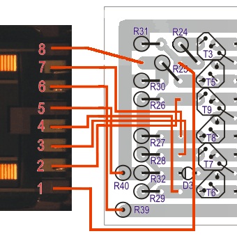
Also probably a stupid question too , but why Keep alive anode and Keep alive cathode is pin different on your Pcb ??
compared to this picture
pgb12201pin.png

pinconnectionpgb12201.png

Here I see Keep alive cathode PIN 6
image1yd.png

here I see Keep alive cathode PIN 5

Thanks igor sorry for trouble !
 
Hm...I have elsewhere hadware datasheet for PBG12201.
You not first man who make this VU, but first who pointed on wrong connection of plasma.
It worked for me and other people.
I will find the datasheet and check again.
BTW, it isn't worth to measure voltages in open collector circuit without load
(useless).
For now.
Picture of working meter, exactly same as yours, 10 minutes ago ( it is still alive :)
http://i251.photobucket.com/albums/gg291/diy33609/P1030755.jpg
http://i251.photobucket.com/albums/gg291/diy33609/P1030752.jpg
Voltages on PIC, 1dbv (1V RMS) input, at zero of plasma scale, like on picture:
http://i251.photobucket.com/albums/gg291/diy33609/P1030754.jpg
http://i251.photobucket.com/albums/gg291/diy33609/P1030753.jpg
1 0v
2 0v
3 0v
4 0v
5 0v
6 +1.6v
7 +1.6v
8 +1.6v
9 +50mv
10 2.3v
11 2.3v
12 0v
13 0v
14 5v
15 0
16 0
17 +0.48v
18 +0.48v

Your voltages can be different, because different dc voltmeters shows different
readout on impulse signals and your vu meter pots can be adjusted for different scale.
Anyway, it should work, and 99% the prob is not pic or pbg.
Maybe, PIC's port shorted and gone..., but I'd check signals on pins 6...11 of PIC with scope.
With different plasma readings some of them can be different, but here is what you get in general.
http://i251.photobucket.com/albums/gg291/diy33609/P1030758.jpg
http://i251.photobucket.com/albums/gg291/diy33609/P1030756.jpg
http://i251.photobucket.com/albums/gg291/diy33609/P1030757.jpg
IMHO, something wrong in between PIC and plasma.
When you waiting or scope, check with multimeter all values, polarity's here.
Let me know about results.
 
OMG!!!! Please see plasma wiring at my picture...seems....
ah, yes, and install jumpers or check connections are same as my jumpers on pcb-
they connected for log scale, peak measuring.
Holy ****!!!
I can't see your plasma connection, but something tells me..... ;)
 
Igor  :D :D :D :D

You point me on the right direction ...
After desolder the switch Pcb ( RMS/PK ) and resolder  jumpers instead ... Turn On  ... First nothing change but i finally choose to try with the second plasma and ...now it Work !!  :D :D :D

Dont Know why the first is apparently dead ... maybe when i ve try to test it or maybe when i ve inverse Keep alive anode and Keep alive cathode . ( Yes yes i ve try yesterday sorry  :-[ ) 

SO I MM SO HAPPY  .... ;D ;D

1/ About the PBG connection i was talking about last post here 
schemapbg.png

cablagepgb.png

Seems His Pin going to plasma are different from schema  so different than what we do ( but it work ... ) 

2/ I notice one thing trying to adjust with  1K sinus the plasma left and the right together ..
  After trim them
pbglevel1.jpg

when i put the level down  i got 3 led difference  at the end  of plasma  ..
pbglevel2.jpg


Just curious about a way to correct it ??  :D

And many thanks igor for your Help !!  ;D ;D


HURRAY!!!!

I will check if I have another plasma. I checked them before sending, they were 100% OK.
Regarding the offset.
TL072/74 etc op-amps sometimes have few mV of DC offset. At 50dB scale, we need opamp
with good dc precision.

I had some times same prob with opamps, my guess is simply use AD713/AD706
or take some spare op-amps and try to choose ones with better dc characteristics.
 
Hi Igor,

I've had my display up and running for over a year now I believe. It's great. The other day though, the lines on the bargraph started jumping around. Wait, what? It's a meter, right? That's what its supposed to do. Heh heh. What I actually mean is that when using a test tone, for example, up to a certain level the meter looks solid and consistent between L and R channels. Once I get above a certain level the highlighted segments are no longer aligned between the channels. They are off from each other by 3 segments; and the meter sometimes jumps up and down even with a stable test tone. When its jumping up and down the highlighted segments are jumping between their proper location and 3 segments off. Do you have any idea what I should look for when I pull this apart to check it out?

Thanks,

Josh
 
Josh: seems plasma display get old. Try to adjust the +245V lower, it probably will be better on 210...230V
(no "jumps").
 
Hello!
I have a question about C10 in the PSU : may I use a 47pF (250V) or 63pF (250V) instead of 56pF (200V) (as asked in BOM) ?
I can't find the right component on Farnell (europe).
Thanks!
 
hello together

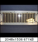
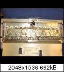
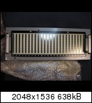
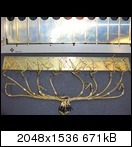
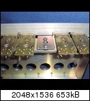
i found from this  two units : ;)


only the mechanical effort must 1984 several thousand german mark have cost, hold still German workmanship!
now, I unfortunately had to disassemble it and a Board must obtain first to me to test the vishay´s !

kind regards
 
Nice project,

does anybody know if the source code for the controller is available.
this way I can build 1 with some modifications

jef
 
Back
Top