Harrison Ford Filter Feeler

GroupDIY Audio Forum

Help Support GroupDIY Audio Forum:

This site may earn a commission from merchant affiliate links, including eBay, Amazon, and others.
The 8-channel version is in the works, too ;-)
Btw, I sent you a mail a few days ago to your gmx account, but you didn´t reply. Are you still using this account?
 
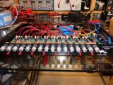
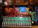
Finally I finished my 8 channel unit, after all those years.... Thanks to Rafael, Marc-Allen and Dan for making this project possible!


https://www.directupload.net/file/d/6135/cdul4atd_jpg.htm


https://www.directupload.net/file/d/6135/fiwehraw_jpg.htm

I know, the wiring needs some more TLC, but I have to take it apart again. A pot is broken and needs to be replaced.
 
Sorr said:
The original Schematic link doeskin work. Where can I get it?

https://web.archive.org/web/20140722133157/http://strangeweatherbrooklyn.com/sales/harrisonfordfilter.jpg
 
Am I right in thinking that the switch is two position, so either both filters are engaged or both are bypassed? I'm pretty sure this has been answered I just want to be sure Im understanding it correctly. If so, and I were to not include the switch, I would just have to put three jumpers in instead of the switch?

And does anyone have the BOM? The link on page one seems to be a dead end.
 
Correct. The switch is not a true bypass switch and yes it disengages both filters. You can certainly leave the switch out and I seem to recall that a user installed a true bypass switch earlier in the thread.
 
Thank you j.colt, I'll be adapting these to 500 series and was looking at jensenmann's wiring of the switch. It left me a bit confused to say the least. This is the first time I'll be adapting a circuit to 500 series and wiring switches just throws me off for some reason. But given how I plan to use these I wont need the switch and could always revisit it later. I also now realize the BOM is written out on the first page, so pardon my ignorance... it was late.
 
Am I right in thinking that the switch is two position, so either both filters are engaged or both are bypassed? I'm pretty sure this has been answered I just want to be sure Im understanding it correctly. If so, and I were to not include the switch, I would just have to put three jumpers in instead of the switch?

And does anyone have the BOM? The link on page one seems to be a dead end.
You'll need two jumpers to bypass the switch. Here's a pic of my version, I also bypassed the switch and added true bypass. Maybe that helps...
 

Attachments

  • DSC02480_01.jpg
    DSC02480_01.jpg
    124.9 KB · Views: 134
Hi all,

I'm having some trouble sourcing the pots from Colin at Audio Maintenance. I don't see the OM-01-028 pots on his site anymore and he hasn't replied to my request if he will be carrying them. Which is OK because I can source them directly from Omeg.

However, it's cost prohibitive to order just the switches from the UK (I'm located in the USA). Unfortunately, I can't find the equivalent of the switch called out in the thread: Audio Maintenance Limited AL-03-001 - 2 Pole Changeover Switch (PCB Mount) - Latching

So... does anyone know if something like a C&K F2UEE would work? It looks like its pins may be close, but not exact wrt the PCB footprint.

Thanks!

Untitled.png
 
Last edited:
Hi All

I'm going to make that build but I'm a bit confused about the pot!
On the 1st post of this thread it's write : 47k Rev Log pots (from AML) and below there is a BOM where it's write 50k Dual Lin ! So, which one is need !? I mean LIN or Rev LOG ?
Also seems like the Omeg 47k is not anymore on the AML catalog... i can't check there for get info... If you have any tips or model references to get one closer it's welcome...

thanks
F
 
Last edited:
Hello to all,

I'm from Croatia, and I'd like to make a filter for myself. Please does any have file for PCB?

Thank you in the advance.
 
Sorry for my newbie-question but I'm trying to learn something while building these boards.

I'm populating the boards right now but for C8 and C9 I only have 100uF rated at 16V in stock. This should be fine right? The boards run +15/-15 VDC from what I understand, or should I be thinking of it as 30 VDC betwen +15 and -15? Trying to look at the schematic, but I'm to novice to secure my thoughts in a decision. And while we are at it.. These capacitors, are they bypass capacitors (decoupling caps?) for filtering out possible high frequency noise? Or are they something else since polarity is involved?

I should add that I'm going to use a toroidal trafo -> linear PSU -> filter boards

Thanks :)
 
16vdc will work but you wont have much headroom for any potential over voltage if your regulator gives out. 25vdc would be a big as you'd need to go if you decide to use something bigger then your 16vdc caps.
 
Back
Top