KA-Electronics.com Mastering Tools, Kits, Vintage Semiconductors, Power Supplies and More

GroupDIY Audio Forum

Help Support GroupDIY Audio Forum:

This site may earn a commission from merchant affiliate links, including eBay, Amazon, and others.
Triad-Utrad Transformers

I originally posted these links in Technical Documents and used external links because 2 of the 3 files were too big to attach.
Despite external links being posted in the same thread by other users due to size I was specifically singled out by a member who complained.
My post was removed. The other external links remained.

I receive no benefit from hosting these links and I provided them as a courtesy to the community.
In order to make them available to the community who does appreciate them I'm posting them here.

Triad 1961 Catalog (pdf 16 MB)

Triad Utrad 1973-1974 Catalog (pdf 22.8 MB)

Triad Utrad 1987-1988 Catalog (pdf 21 MB)
 
Triad-Utrad Transformers

I originally posted these links in Technical Documents and used external links because 2 of the 3 files were too big to attach.
Despite external links being posted in the same thread by other users due to size I was specifically singled out by a member who complained.
My post was removed. The other external links remained.
Sorry you had that hassle Wayne.

Your hosting is appreciated.
 
Pico Compressor Stereo Edition PC Board and THAT4301 ICs available.

I just found a source for a small quantity of NOS THAT4301P that were purchased by a client when the parts went last time buy and have bundled them with the very few remaining Pico Compressor boards I held on to.

There is one Pico SE PCB with ICs currently available here: Pico SE THAT4301-based Stereo Compressor, Bare PC Board and ICs

I'll supply a zip file of documentation at the time of shipment.
I just put another PicoSE + THAT IC kit in the store. I needed to wait until a couple of sold boards arrived at their destinations before adding it.

EDIT: 3/29. This board sold but there will be another one available once some boards currently in transit arrive at their new homes.
 
Last edited:
Back in 2018 emrr sent me a pdf of the Studer 1.914.533 "90° Filter" and a link to this post: Studer 1 194 533. 90 degree shifter. LTspice file

In 2021 I got bored, decided to Protoboard a "Dome" filter and gave it a listen. The experiment led me to believe it had some unique, somewhat niche, applications. The Studer "90°" Dome Filter Stereo to Mono Quadrature Summer - Pro Audio Design Forum

When stereo is summed to produce Mono all the L-R information is lost. By phase shifting the L and R inputs so they are 90° out-of-phase L+R and L-R are both preserved and folded into Mono with equal weight. For Wide elements the I+Q output sounds more similar to the stereo version and has more equal signal power than L+R. It solves the "disappearing elements in Mono" problem during tracking and/or mixing.

Once I get something on a Protoboard the only way to get the Protoboard back is to do a layout. So, five years later, I did one. I'm not sure which is the greater victory - having a new product and tool in my toolbox or getting the Protoboard back. You decide. In any case here's a preview of the board.

Quadrature_Summing_Filter_PC_Board_Assembled_1200.jpg


The Quadrature Summing Filter has two inputs and can output, through relay selection, Stereo, Mono (L+R)/2, and the Quadrature Sum known as I+Q/1.4. There are also separate I and Q outputs for synthesizing Width from a mono input or level detection for dynamics or instrumentation applications. A jumper provides for Left and Right Stereo inputs or, in an alternate position, feeds the Left input to both channels' I and Q all-pass filters.

I'll be making the board available on the store soon for those wanting to experiment.
 
Last edited:

Quadrature_Summming_Filter_PC_Board_Assembled_1200-1024x768.jpg

Boards are now available for those wanting to experiment with this unique, niche tool.

https://ka-electronics.com/shop/index.php?route=product/product&product_id=175
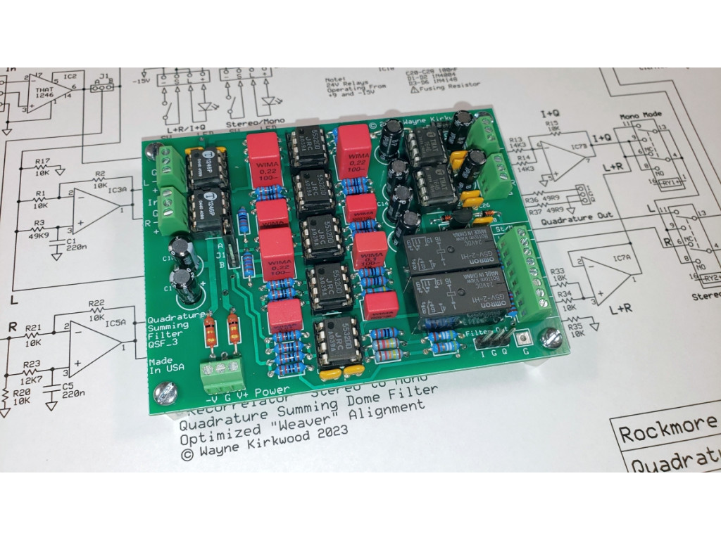
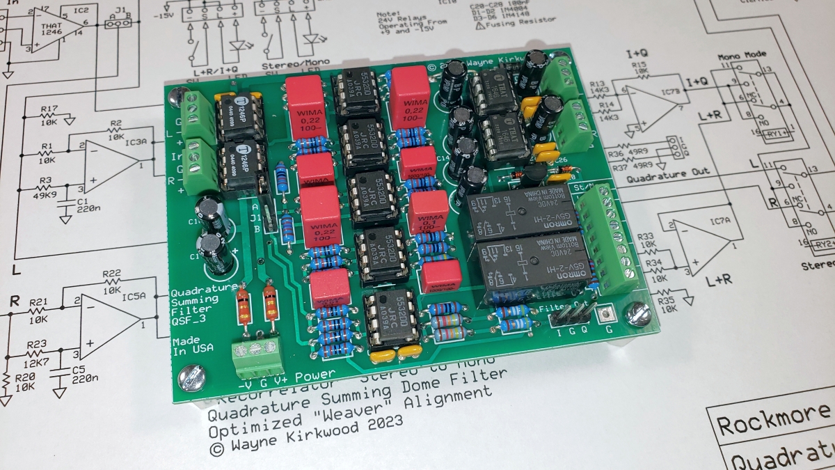
The KA-Electronics "Quadrature Summing Filter" board solves the problem of disappearing elements and audible changes when uncorrelated L-R difference information is lost during conventional L+R mono fold-down.

One common complaint solved by the Quadrature Summing Filter are keyboards whose stereo output changes when folded down to mono. Applications to studio recording include tracking and mix-down where a stereo keyboard is folded down to mono and then positioned in the mix by conventional in-console panning.

For mono mediums, such as AM broadcast or in-store background music, the Quadrature Summing Filter provides a product which sounds more like its' stereo counterpart and retains the original's signal power.

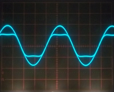
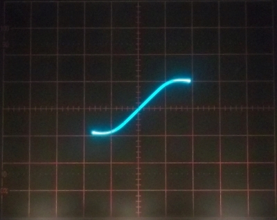
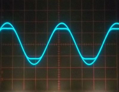
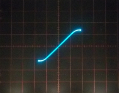
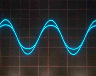
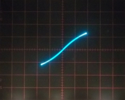
The Quadrature Summing Filter works by phase-shifting the Left and Right channels so they have a near-constant 90° difference between them throughout the audio spectrum. The phase-shifted paths, often called "I" and "Q," are then summed into "mono." The result is that in-polarity elements (L+R) and out-of-polarity elements (L-R) are summed into the final output with equal weight. L-R's contribution is equal to L+R's rather than L-R cancelling fully. The result is an output that sounds more like the input having nearly the same signal power and instrumental balance without the "sucked-out" sound of conventional mono.

Three Output Modes

The Quadrature summing filter accepts fully-balanced Left and Right inputs and provides the following three output modes:

Stereo forwards the Left and Right inputs to the Left and Right outputs providing buffered bypass.

Mono L+R adds the Left and Right channels with a -6 dB gain coefficient and forwards (L+R)/2 to the Left and Right outputs.

Mono I+Q adds the Left and Right channels in 90° quadrature with a -3 dB gain coefficient and forwards (I+Q)/1.4 to the Left and Right outputs.

Relay Mode Selection

One relay selects either L+R or I+Q Mono.

An additional relay allows selection between Stereo and Mono. Using the relays is possible to A/B compare any two sets of modes using a single button press.

Current-limited outputs are available to drive mode LEDs. An on-board 24V relay supply, not referenced to audio ground, is provided.

Auxillary I and Q Outputs

Buffered separate I and Q outputs are available on a header for instrumentation and "mono to stereo" width generation.

Balanced Inputs and Outputs

The inputs are fully-balanced using THAT 1246 line receivers. THAT 1646 OutSmarts® ICs drive the outputs.

Mechanical and Power Specifications

The board requires +/-15V at approximately 100 mA including external LEDs. No relay supply is required.
The board dimensions are: 3.7" x 2.75".
Mounting holes: #4/M3 0.125" dia on a 3.4" x 2.4" grid.

Audio Specifications
  • Inputs: THAT1246. Input Impedance 24KΩ differential, 18KΩ common mode. Maximum input level +27 dBu.
  • Outputs: THAT1646. Output impedance 50Ω nominal. Maximum output level +27 dBu.
  • Aux I and Q Outputs: Buffered, output impedance 50Ω. Maximum output level +21 dBu.
  • I and Q Differential phase accuracy: ±3° 30 Hz -16 kHz.
  • I+Q Summed Frequency Response: ±0.5 dB 30 Hz - 20 kHz for in or out-of-polarity inputs.
  • Noise: Stereo -99 dBu, -101 dBu A-wtd DR 126 dB; Mono -100 dBu, I+Q -94 dBu -96 dBu A-wtd DR 121 dB.
  • Gain: Stereo 0 dB; Mono 0 dB with equal in-polarity L and R inputs; I+Q 0 dB with equal in or out-of-polarity inputs.
  • Distortion: Stereo, output level +20 dBu into 10KΩ load. 1 kHz THD 0.0001%, primarily HD3.
Note: Noise measurements are for a 20-20 kHz bandwidth and are unweighted unless specified. Maximum level specifications are for ±15V supplies.

Additional audio specifications and performance as they become available.

The construction thread for the Quadrature Summing Filter is featured in the Pro Audio Design Forum.

The Quadrature Summing Filter is sold as either a bare PC board, a "kit" including THAT1246, NE5532 and THAT1646 ICs, or an assembled and fully-tested module. A Mouser Electronics Project Manager bill-of-materials is available for DIY builds of the Quadrature Summing Filter.​
 
Found them. That was the SC_108 Sidechain board.
 

Attachments

  • Pico_SC_108a.GIF
    Pico_SC_108a.GIF
    36.6 KB · Views: 0
  • Pico_SC_108_Silkscreen.GIF
    Pico_SC_108_Silkscreen.GIF
    20.5 KB · Views: 0
  • Pico_SC_108_Relays.GIF
    Pico_SC_108_Relays.GIF
    23.3 KB · Views: 0
Triad-Utrad Transformers

I originally posted these links in Technical Documents and used external links because 2 of the 3 files were too big to attach.
Despite external links being posted in the same thread by other users due to size I was specifically singled out by a member who complained.
My post was removed. The other external links remained.

I receive no benefit from hosting these links and I provided them as a courtesy to the community.
In order to make them available to the community who does appreciate them I'm posting them here.

Triad 1961 Catalog (pdf 16 MB)

Triad Utrad 1973-1974 Catalog (pdf 22.8 MB)

Triad Utrad 1987-1988 Catalog (pdf 21 MB)
The procedure regarding posts to the tech forum have recently been updated/clarified. Posting Guidelines - MUST READ!

JR
 
For those needing an Ultra Low Distortion Oscillator I have a B-stock unit currently in the store that's discounted $30. The PC board had two small bridges under the solder mask on the lower plane that required clearing and mask overcoat. The unit meets full specs and due to the re-work I've decided to discount it.

https://ka-electronics.com/shop/index.php?route=product/product&path=67&product_id=120
ULDO-Nacho_Assembled-1024x768.jpg


I'm finally starting to add detail specifications. Here are the features and specs of "ULDO-Nacho:"

ULDO-Nacho has the following features:

  • Balanced output. The balanced output can also be used to provide two opposite polarity unbalanced outputs.
  • Low Distortion, typically -141 dBc at +20 dBu into 10KΩ; -138 dBc at +20 dBu into 600Ω. For low distortion performance at lower operating levels it's recommended that ULDO be used at approximately +20 dBu and attenuated with "ATTO" or an external pad.
  • A balanced passive notch filter extends measurement A/D dynamic range. The balanced notch filter can also be switched or jumper-selected to provide two independent filters for simultaneous Left and Right measurements.
  • A balanced instrumentation preamp provides 40 dB post-filter gain. The instrumentation amp can be switched or jumper-selected to provide two unbalanced preamps for Left and Right measurements.
  • Common Mode Rejection after the preamp using cross-coupled THAT1246 allows balanced distortion measurement and provides a balanced filter output to feed an A/D converter.
  • Output level is adjustable over a 28 dB range.
  • DC-controlled output level can use multiturn (wirewound) panel pots for precise level control.
Mechanical and Power Specifications

  • Board Size: 6.3" x 3.3" Mounting holes: M3 on a 6" x 3" pattern. Assembled height: Approximately 1" not including stand-offs.
  • Power Requirements: ±15 to ±18V (max) approximately 40 mA with no load current. At the maximum output level of +25 dBu into 604Ω the average current is 56 mA.
Connections

  • Inputs: Power, DC Level Control, Notch Filter Input.
  • Outputs: Oscillator Output, Oscillator Monitor Output, Unbalanced Left and Right Notch Filter Outputs, Balanced Notch Filter Output.
  • Notch filter configuration: Three jumpers to switch between two single-ended or a single balanced filter. A DPST switch may be used to switch modes.
Oscillator Specifications

  • Frequency: 1 kHz ±2%.
  • Maximum Output Level: Balanced +27.5 dBu 10KΩ load, +25 dBu 604Ω load (+25 dBu into 600Ω is 316 mW). Unbalanced +21.5 dBu 10KΩ load, +20.5 dBu 604Ω load.
  • Output impedance: 49.9Ω unbalanced, 100Ω balanced.
  • Distortion: At +20 dBu into a 10KΩ balanced load typically -141 dBc (0 dBc = +20 dBu). +20 dBu into 604Ω (+20 dBm/100 mW) typically -138 dBc. (-140 dBc is 0.00001%.)
  • Output Noise: -90 dBu (typical) unweighted over a 20-20 kHz measurement bandwidth. Spot noise at frequencies greater than 1 kHz is typically -130 dBu. (FFT averaging is required to accurately measure ULDO's residual distortion.)
  • DC level control: -0.4V to -12V for approximately -2 dBu to +26 dBu balanced output level. (Unbalanced 6 dB less.) Unbalanced Vout peak = 1.2 * Vcontrol.
  • Outputs: Oscillator output has high-current ground return path. Oscillator monitor output is to feed notch filter or level meter.
  • Oscillator start-up time: 20-30 seconds from power application to stabilized amplitude.
  • Output level stability: Less than ±0.02 dB at +20 dBu.
Notch Filter and Preamp Specifications

  • Notch Filter Frequency: 1 kHz adjustable to match oscillator frequency.
  • Notch filter depth: Typically 60 dB. Depth is not critical to FFT measurement results as long as the measurement A/D is within its spurious free dynamic range.
  • Notch frequency sensitivity to source impedance: Minimal. The source impedance appears as a common point impedance to the two "Wye" arms of the unbalanced Twin-T filters or the four Wye arms of the balanced input "double Twin-T."
  • Notch filter input impedance: Frequency dependent. Single ended 100KΩ at DC, 53KΩ at 20 Hz, 12KΩ at 1 kHz, 3K8Ω at 20 kHz. Balanced values are twice the single-ended specifications.
  • Notch filter balanced input common mode impedance: Frequency dependent. 50KΩ at DC, 30KΩ at 20 Hz, 27KΩ at 1 kHz, 23KΩ at 20 kHz.
  • Post filter preamp gain: +40 dB balanced or unbalanced. Balanced common mode gain: 0 dB. Preamp inputs are AC-coupled with a 4.8 Hz cutoff.
  • Notch filter and post preamp equivalent input noise: -114 dBu at the balanced output, 100Ω source impedance.
  • Notch filter/post filter preamp common mode rejection ratio: >60 dB. (Balanced output.)
  • Notch filter preamp output impedance: Left and right unbalanced outputs 49.9Ω. Balanced output 100Ω differenetial.
Note: Noise measurements are for a 20-20 kHz bandwidth. Maximum level specifications are for ±15V supplies.​
 
I've been working on a soft saturator off and on since about 2013 and am finally bringing the "Waveulator" to fruition.
Just posted preliminary schematics. There are sound files sprinkled throughout the thread and oscillograms are posted below.
https://www.proaudiodesignforum.com/forum/php/viewtopic.php?p=17253#p17253
You can see in the high ratio images that there are no hard corners as it clips. The corners are "beveled."

Waveulator_Low_Threshold_High_Ratio_Waveform.jpg

Waveulator Low Threshold High Ratio Waveform

Waveulator_Low_Threshold_High_Ratio_Transfer.jpg

Waveulator Low Threshold High Ratio Transfer


Waveulator_Medium_Threshold_High_Ratio_Waveform.jpg

Medium Threshold High Ratio Waveform

Waveulator_Medium_Threshold_High_Ratio_Transfer.jpg

Waveulator Medium Threshold High Ratio Transfer


Waveulator_High_Threshold_High_Ratio_Waveform.jpg

Waveulator High Threshold High Ratio Waveform

Waveulator_High_Threshold_High_Ratio_Transfer.jpg

Waveulator High Threshold High Ratio Transfer

Some softer saturation:
Waveulator_High_Threshold_Medium_Ratio_Waveform.jpg

Waveulator High Threshold Medium Ratio Waveform

Waveulator_High_Threshold_Medium_Ratio_Transfer.jpg

Waveulator High Threshold Medium Ratio Transfer
 
Last edited:
I've been working on a soft saturator off and on since about 2013 and am finally bringing the "Waveulator" to fruition.
Just posted preliminary schematics. There are sound files sprinkled throughout the thread and oscillograms are posted below.
https://www.proaudiodesignforum.com/forum/php/viewtopic.php?p=17253#p17253
I've been following the design in your forum, the samples sound great - seems like it makes an excellent pre-master limiter, as well as a creative clipper. Very excited to see the progress you're making.
 
Thank you for sharing your latest creation. I'd love to build one when they become available
 
Back
Top