KA-Electronics.com Mastering Tools, Kits, Vintage Semiconductors, Power Supplies and More

GroupDIY Audio Forum

Help Support GroupDIY Audio Forum:

This site may earn a commission from merchant affiliate links, including eBay, Amazon, and others.
Just ordered the wav board and some other stuff. Looking forward to the builds. Thanks for making it available.
 
Grabbed 2 yesterday!

I still need to read through all of the documentation but should the 10K controls (makeup, threshold, ratio) have a linear or logarithmic taper?

Thanks for this great project, Wayne!

-Alex
 
Thanks Alex!

The make-up control is definitely linear taper and is calibrated in dB/volt. I use 10KΩ.

I've been using 10KΩ linear taper for the threshold but if it were a stepped switch I'd make it log taper calibrated in -dBFS with "0" being fully clockwise. I need to experiment using a log taper pot which should have a better feel. There's a trim pot on board so the user can set 0 dBFS to whatever the 0 dBFS of the converter is.

For ratio/hardness I've been using a dual linear 10KΩ. For lower-level inputs most of the action is in the upper rotation but for hot inputs the better working region is in the lower half. There's really no definable scale since the combination of linear detection and exponential makes the having a conventional ratio scale ranging from 1:1 to 1:X difficult. A scale ranging from 0-10 using a pot or, for a 12 or 24 step switch, 0-11 seems to make the most sense.

Adjustment of ratio is best metered with the on-board voltage or current gain reduction outputs. A meter plug-in on the A/D provides the full picture: I've been using the K-Meter.

One thing worth pointing out is that the gain reduction circuit meters peak reduction. A 6 dB peak GR indication metered with an RMS or average-responding meter on a sine wave will show less GR since as the signal gets squashed it gets fatter as harmonics are added in. The RMS level decreases at a lower rate than the peak.
 
I wanted to write and thank everyone for their support of the Waveulator and other widgets.

Some of you have already received your Waveulator boards and the rest are on their way. I've had to build some boards the last couple of days and can now return to documenting Waveulator final checkout and test instructions. Thanks again everyone!
 
Thanks for the detailed response on the pot tapers. For the ratio pot, I was planning on building the controls stepped but I’ll experiment around with 10K pots with different tapers before populating the switches.

Trying to finalize the panel design before proceeding, it’s almost there! Bought a hole saw kit for the mA meter, fingers crossed my drill press doesn’t lock up while using it.
 
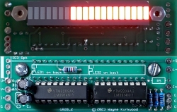
I just received a run of 20 segment LED gain reduction boards similar to the original Pico GR-20 and have pics of the prototype.

I added some additional powering options and the ability to switch it to dot mode. It uses the LM3914 which are still widely available on Amazon, eBay and are also now made by HLF.

My motivation was to provide an LED GR meter for the Waveulator but this meter, with its 2.4V FS input, is suitable for other linear dB applications including the original Pico and dBx clones.

GR_20_PC_Board_930.jpg


GR_20_PC_Board_Front_Back_250.jpg

GR20 Gain Reduction Meter, Actual Height 1.0" Width 3.1"

Now available in the KA Store: Gain Reduction Meter - 20 Segment Bar Graph - Linear 2.4V Full Scale

Schematics are here: Gain Reduction Meter - 20 Segment Bargraph - Pro Audio Design Forum

More stuff at KA Electronics/Rockmore-Labs
 
Last edited:
What would it cost shipping to Belgium included one and 8 LED gain reduction boards?
 
@tommia Thank you for inquiring.

International shipping via First Class to most international destinations is around $18.50 US for the first 8 ounces.

Most single boards, or 8 GR meter boards - with packaging - can be shipped under 8 ounces.

I will have a greater quantity of GR meters available for shipment in a few days. Some of the first run of 10 are already sold. I'll post here when they come in.

On another topic I'm getting in some LM3914N from Amazon in a couple of days from two different vendors. One has TI markings the other apparently Chinese but not HLF. Curious as to how these will work out. I think some vendors are buying TI die and packaging them. My suspicion is the reason TI discontinued the LM391XN and not the "V" version is that they were done buying and using 18 pin DIP lead frames. Just a guess though.

There is an HLF vendor who has LM3914, LM3915 and LM3916 in the UK on eBay. I exchanged email with Raimonds, the shop owner, and turns out he is an authorized HLF distributor and synth builder. His eBay store listing for the LM3914 is: 10pcs Deal LM3914 Dot Bar Display Driver HLF Original IC Chips Sale Uk Stock | eBay His shop is: svinavate For whatever reason only two of his items appear on the US site; the UK site has his full store. HLF appear to be manufacturing these as they offer the LM3915 and LM3916 which TI no longer produces.
 
Last edited:
There must be a better way. Let's say a pcb of $60. Shipping on your website $19,5. Handling fee of shippingcompany (post office) €18. Import taxes and vat after that is 16 % and 21%. Total of $136 that is 226%.
 
@tommia I'm sympathetic to the high cost of importation but there's not much I can do other than to suggest that you do your own layout and have your own boards made.
 
Well, you could produce your pcb's in europe and a member (could be me) can do the logistics. I can imagine you don't share gerber files.
 
That's a thought and I appreciate the offer. I did something similar for Markus' insert switcher and eventually bought his Gerbers.
 
Well, you could produce your pcb's in europe and a member (could be me) can do the logistics. I can imagine you don't share gerber files.

That's a thought and I appreciate the offer. I did something similar for Markus' insert switcher and eventually bought his Gerbers.
I’m sure a few of us on this side of the Atlantic would appreciate the offer too.
 
  • Like
Reactions: prd
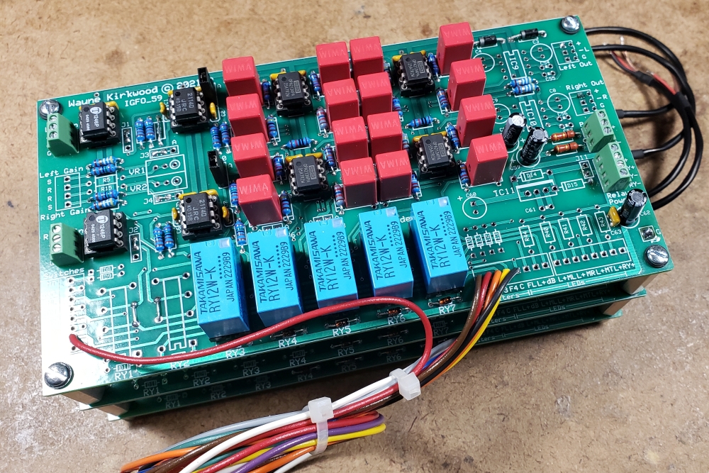
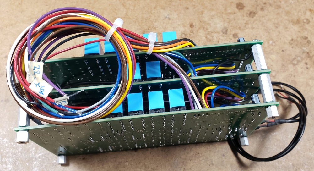
Before I ship it out I wanted to snap a couple of pics of a recent 10 Filter Input Gain Filter Output "IGFO" board stack I made for a client.

There are 4 HP filters on the top board for 20, 30, 40 and 50 Hz. There is no gain switching other than a +6dB mode.
The second board is a split HP/LP combination handling 60 Hz HP and 12 kHz LP.
The third board, on the bottom, handles the 14, 16, 18 and 22 kHz LP filters along with the final THAT1646 output.

The boards are sandwiched by threaded hex spacers. I used cut-off 4-40 screws to make 4-40 all-thread for the second and third boards.

IGFO_10_Board_Stack_1.jpg

Input Gain Filter Output IGFO board stack.

IGFO_10_Board_Stack_2.jpg

Input Gain Filter Output IGFO board stack.

The filter frequencies are under relay control and require only a one pole rotary switch for both channels' LP filter and a second rotary for the HP. Though it might seem easier to simply switch filter components, the IGFO board uses a bank of filters and inserts only the selected low and/or high pass filter into the signal path. For stereo, two 4 pole rotary switches would be required but when preview for vinyl cutting is added, which is often the case, the two required switches grow to 8 poles. The "bank of filters" approach reduces the rotary switch requirements to one pole. The wiring pigtails for the rotary switches will be terminated by the customer and can be seen hanging off to the side.
 

Latest posts

Back
Top