You are using an out of date browser. It may not display this or other websites correctly.
You should upgrade or use an alternative browser.
You should upgrade or use an alternative browser.
LA-4 Help Thread!
- Thread starter Luny Tune
- Start date


Help Support GroupDIY Audio Forum:
This site may earn a commission from merchant affiliate
links, including eBay, Amazon, and others.

Luny Tune
Well-known member
Nice work, Zpliff! Good job on making it fit in there. Nice little detail with removing the PSU part from the bords. So I guess you have a spare PSU board for some other project now! ;D
@ilfungo
What's different about the 11148? I mean, no other transformers need the added cap...?
@ilfungo
What's different about the 11148? I mean, no other transformers need the added cap...?
Luny Tune
Well-known member
Should work fine, I think. The rule of thumb says that 18V AC rectified is 25,2V DC so 35V gives you a little under 10V of headroom. I'm sure that'll be fine. Maybe the caps will live a bit shorter but hey....then just change them. It's diy... ;D
...a bit longer, or am I missing something?Luny Tune said:... 35V gives you a little under 10V of headroom. I'm sure that'll be fine. Maybe the caps will live a bit shortery...
Great project BTW.


Luny Tune
Well-known member
@syn
Well, you're commenting on the fact that there is a headroom and that this means the caps will live longer. That's true in itself of course. But, muffy1975 is replacing the caps specified for the board which are rated at 40V. So the 35V is less than what's specified, thus sparking his doubt.
Well, you're commenting on the fact that there is a headroom and that this means the caps will live longer. That's true in itself of course. But, muffy1975 is replacing the caps specified for the board which are rated at 40V. So the 35V is less than what's specified, thus sparking his doubt.

Luny Tune
Well-known member
I'm not sure, but the resistors surrounding the LDR in the input seem small to me. I would think they're making the LDR work in it's extreme low resistance range and thus giving it very very fast attack and release times. Look at the VTL5C4/2 datasheet and see how steep the curve is in that range of resistance. The rule of thumb is that it will start to become a factor in the circuit when it comes below 10 x the resistor values it's interacting with.
In the LA-4 we're forcing it to work in the other end of it's range by putting a 150 kΩ resistor in front of it. That's R102 in this circuit. BUT in the LA-4 it's presented with a high impedance input (the opamp) on the other side of the LDR so I'm not sure how to adapt those principals to this circuit.
Sorry, but I can't help more than that....and I realise that's not much!")
Merry christmas!
In the LA-4 we're forcing it to work in the other end of it's range by putting a 150 kΩ resistor in front of it. That's R102 in this circuit. BUT in the LA-4 it's presented with a high impedance input (the opamp) on the other side of the LDR so I'm not sure how to adapt those principals to this circuit.
Sorry, but I can't help more than that....and I realise that's not much!
Merry christmas!
ilfungo said:sorry Luny
I repeat a question that I had long ago ....
from various projects I have left two edcor XSM 10k/10K
May be fine for this project?
There are no changes to make?
Thanks
I believe you need something like 600/600 Ohms of impedance. Those you have are 10k/10K, but you can always
try them and listen........
Luny Tune
Well-known member
MrZpiff is right. You really should just try them out. As I've mentioned before, I've successfully tested odd trannies in the circuit. The very small, very very cheap and otherwise crappy trannies from Mouser and other shops actually sound surprisingly good in this circuit so don't hesitate to try out whatever you have lying around.
Rybow
Well-known member
Its been a long time, but I have finally finished my 2 channel unit. Well, almost. I just need to replace the VTL 5C4's with one VTL 5C4/2 as I am having trouble calibrating. Channel one has the VTL 5 C4's with an OEP a262a2c, MC33079 in the sidechain, and the resistor mod Luny outlined earlier in the thread. Channel 2 has the NSL 32, cinemag CMOQ 2S, and also has the mc 33079 in the sidechain. The channels are quite different from each other. Channel one has a thicker and smoother sound, while channel 2 is more transparent, and can be prone to distortion at high GR. The distortion sounds good though. These have become my go to comps for bass, vocals, and clean electric/acoustic guitars. I can't believe I got these working! Big thanks to Luny for the project, and everyone on this thread that helped me out. Here are some pics:
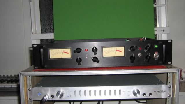
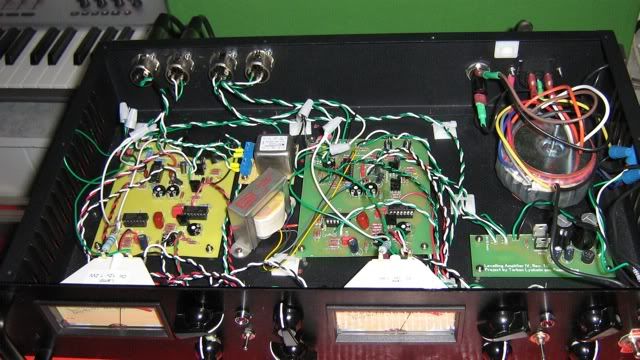
As you can see it looks very DIY. I did the panels by hand. The meter cut outs took forever, and I am surprised they came out fairly straight. Since the unit looks like this, it comes with built in theft prevention. As soon as the opto's show up, I'll do one last calibration, and then finally rack this puppy.
As you can see it looks very DIY. I did the panels by hand. The meter cut outs took forever, and I am surprised they came out fairly straight. Since the unit looks like this, it comes with built in theft prevention. As soon as the opto's show up, I'll do one last calibration, and then finally rack this puppy.
dustbro
Well-known member
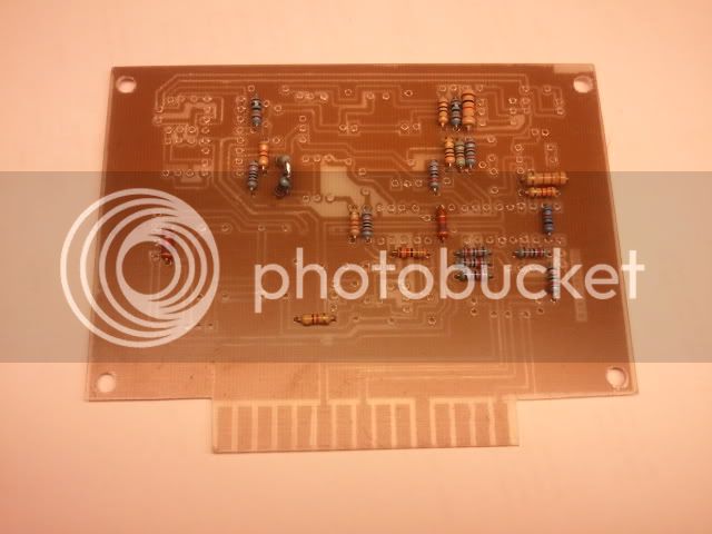
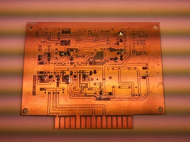
I finally had some time to finish my 500 series LA-4 design. Just etched the board, and I cant wait to slap it together and do an initial test.
I swapped out one of the TL074's with a TL072 since half of the chip wasnt being used in the original design.
I swapped out one of the TL074's with a TL072 since half of the chip wasnt being used in the original design.
dustbro said:I finally had some time to finish my 500 series LA-4 design. Just etched the board, and I cant wait to slap it together and do an initial test.
I swapped out one of the TL074's with a TL072 since half of the chip wasnt being used in the original design.
Amazing work,
it looks great.
Let us know how it turns out
Luny Tune
Well-known member
Unbalanced:
Ground on pin 1 and signal on pin 2. Short pin 3 to pin 1.
Common mode rejection...what? Are you not sure what it's about or how to adjust it?
Ground on pin 1 and signal on pin 2. Short pin 3 to pin 1.
Common mode rejection...what? Are you not sure what it's about or how to adjust it?
Similar threads
- Replies
- 0
- Views
- 3K
- Replies
- 38
- Views
- 10K