Neumann U67 Clone : D-U67 Tube Microphone Build Thread.

GroupDIY Audio Forum

Help Support GroupDIY Audio Forum:

This site may earn a commission from merchant affiliate links, including eBay, Amazon, and others.
tonitu said:
Hi Dennis, I also had the same problem , Even if it does not burn the diode , 22 VAC in the heater line is too high when you dont load the PSU, and the diode can burn. In Spain the line can vary from 205 Volts to 235, this cause a lots of problems in this kind of regulation. Dan told me : Please no more than 20 vac in the heater!!, and it works perfectly. When the line is near 220vac, No problem without load, whem rise a little the temperature in the zener is critical.  Hope this help.

I repaired Dennis' PSU in the meantime, he had a short circuit between the B+ and the heater.
Make sure that you don't connect the 22ohm and the 6.8k resistor legs!
I think it is always better to test the PSU with loading resistors - approx  33ohm/2W for the heater and 230kohm/0,6W for the B+,make sure the voltages are not drifting too much, I'd test every PSU for 1hour at least.
 
Howdy,
Has anyone experienced a difference between both sides of the capsule in figure eight. Not sure if the difference is the capsule itself or the circuit. Not sure what to check. I have tried two quality capsules, and both exhibit a noticeable difference. Seems like maybe a difference in low end response or general reach/closeness between the two sides.

Dan
 
Yes, I'm wearing phones when I notice the difference. I don't think I have ever recorded the back diaphragm or the mix in figure eight.

Dan
 
There can be some sound difference between the two sides, especially on single backplate capsules.
Or on older capsules where the front has been used (and spit on) much more.

But do keep in mind, particularly when listenig on cans, that figure eight has the back in reversed phase.
 
Keep in mind that when listening through headphones, the phase (polarity) of both halves of the microphone listening in figure-8 is different! So to get a good idea, you should swap the phase of the headphone when listening to the rear diaphragm.
(I can always hear if the absolute phase of a microphone is correct when listening through headphones. If the phase is 'wrong', it will sound 'different' and unpleasant.)
 
Hi Everyone,
I'm building my first U67 and I have a Hum issue
I Followed the grounding schem a few pages ago and it seems it have solved the problem
but ! ( yeah there is always a but :) )
when I lift the ground , I have a 110V Between the PSU chassis ground and the mic body ???
even if the mic is not powered on !!! what is weird is that I'm in EU and with 230V plugs

my other question is about the light :
If I want to power a bulb can I take the power from the PCB ( like the -6.3V ) I guess not but just asking :)
 
This 400M resistor from
the BOM has a 10 week wait.
It doesn't seem to be available anywhere else.

http://www.mouser.com/Search/m_ProductDetail.aspx?Vishay%2fRNX038400MFNLB%2f&qs=%2fha2pyFadujywXEGuzeD%252bq3rwhlV1ZspileheGwd%2ffz2HUFbJENkOA%3d%3d

Does this look like a suitable replacement?  Its only temperature rated to 110 C instead of 150 C.

http://www.mouser.com/Search/m_ProductDetail.aspx?Ohmite%2fSM102034006FE%2f&qs=sGAEpiMZZMu61qfTUdNhG%2f3lrKRy06awE%252bMobBJwft0%3d

Thanks and cheers!
 
Hey Vitopower,

they should work as a replacement, the leads are a bit thicker though, so you need to check that they will fit the holes on the pcb.
Other than that they look ok.

Hope that helps.

Moshe
 
I feel the need to weigh in here.

Good luck on your builds everyone. But I must urge all to pay attention to the high impedance section of this mic and the switches. It is a challenge and must be kept clean and tight or problems are inevitable.

Having built loads of electronics and mics over the years this one was like working on watches which I also enjoy!
 
Yes, I agree pip, one of my first builds was this u67 and I used a Sowter 1304 that Brian wound for me and I thought everything was fine but became unhappy with the mic after a while as the clarity just wasn't there. I just didn't plug it in after that for a while as I just wasn't into the sound and started using the Elam 251 instead, I then thought about building another and having a stereo pair.
I wound my own transformer and used a cheaper capsule rather than Eriks version.
To my amazement when i plugged it in, it sounded excellent, not how I remember the first one sounding!
I then spent sometime taking the other one apart and checking all wiring.
Sure enough a silly mistake was made, I resoldered and tested and at last the mic came alive!
So yes, take your time people and double triple check every solder.
 
Hi! I'm finally building my D-67 and I've noticed the PSU pdf isn't complete. At least when I download it the last 8 pages are blank. Does someone have the full document? I guess in the last pages should be the test procedure, which would really help! Thanks in advance!
 
Well, I saw there's a simple test procedure at the end of the mic assembly pdf, so I guess that's all there is, and that the fact that the last 10 pages in the PSU pdf are just white pages is actually intended. I'll keep on soldering and hope for the best!
 
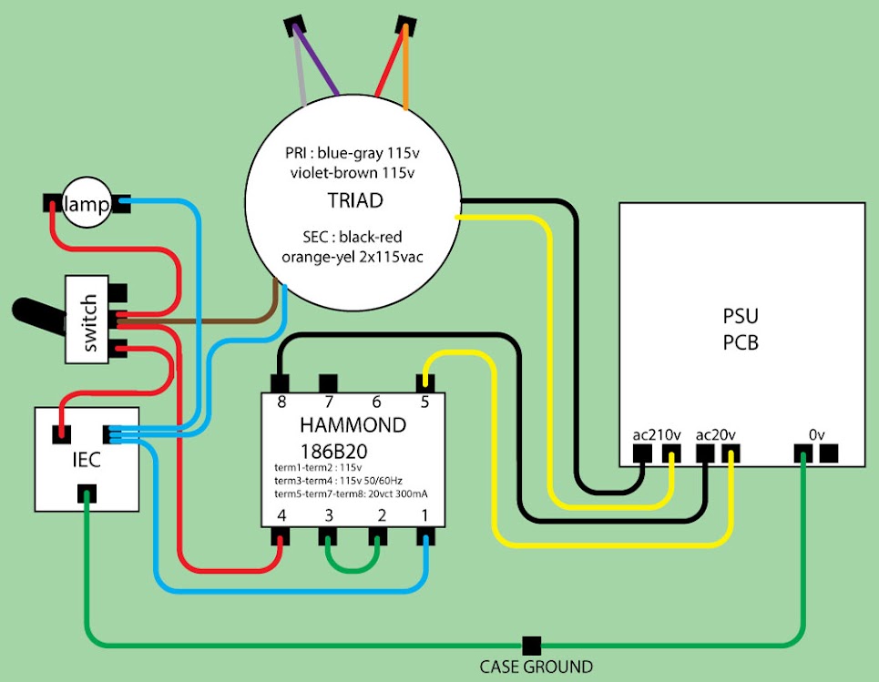
Hey, is someone able to repost the PSU Wire circuit for Europe, tskguy posted it once? Found only one for 110 V.
Edit:
Was searching for a while and found the picture below.
HERE IS WHERE I FOUND IT: https://groupdiy.com/index.php?topic=50021.440
europe-PSU.jpg
 
Update on PSU Power Specification

Problem : R2 is getting way too hot
it has been brought to my attention that the PSU Power Supply (R2) Power was out of tolerance and heating passed its
ratings. this has been very isolated case only.

Explanation: the Hammond transformer in the BOM was specified at 300ma 6VA , some DIYER used higher power supply rating cause a bigger Voltage drop in R2 than anticipated supplying more current to it causing the resistor to get too hot and melt the solder on the pcb. those who have used the Specified Hammond transformer can go ahead and only upgrade R2 for the new higher power resistor if needed.  Those who have the old hammond transformer should be ok as it cannot outpout enough power to go past 2W specified, only a resistor upgrade is need in this case.

Solution: After Analysis of the power dissipation required on R2 to provide with the Heater Voltage. it has been found that the curent hamond transfomer is too much on the limit and the voltage provided after rectification is a bit high for no reason.

The Hammond transformer can be replaced with this part if problem arise and should be used in new build as well
the bom has been updated already, it also contain a new higher power R2 Resistor 22ohm 5W to alleviate this as well and it will run cooler. it is also recommended that R2 and the Zener diode shall be lifted a little bit from the PCB to permit better heat disspipation to run even cooler :


Here is the new transformer part  it is dual primary so it will fit in all country. it will output 16V instead of 20V allowing less dissipiation.

http://ca.mouser.com/Search/ProductDetail.aspx?R=DP-241-4-16virtualkey59820000virtualkey530-DP-241-4-16

Here is the 2 suggested part for R2 as well updated in the BOM

http://ca.mouser.com/Search/ProductDetail.aspx?R=RWHSE09TU025R0FSvirtualkey58440000virtualkey605-RWHSE09TU025R0FS

or

http://ca.mouser.com/Search/ProductDetail.aspx?R=AC05000002209JAC00virtualkey59420000virtualkey594-AC05W22R00J

Many Thanks To TLRT for catching those potential issues.
Best,
Dan,


Latest posts

Back
Top