newbie builds ioaudio MK47 microphone

GroupDIY Audio Forum

Help Support GroupDIY Audio Forum:

This site may earn a commission from merchant affiliate links, including eBay, Amazon, and others.
chunger said:
Another quick question.  Is it ok for me to use 2 LED's in parallel here?

Why would you want to?

Be careful about the mA rating of the LED you choose:  that transformer is 25VA, which means to get 230V with the secondaries in series it can only put out about 100mA or so.  A 20mA LED will take about about 20% of your current budget all by itself:  two of them nearly half!

I would select a low current / high efficiency LED if you can.  Or, if you don't mind changing the hole slightly, there are a ton of good 120VAC lamp indicators that you can hang off the primary after the switch and then you don't have to worry at all! ;)
 
Why not put in a jewel lamp?  They look great and you have the power coming off the Antek trafo already.  I am actually going to do both the lamp and led on opposite sides of the case. 

This is the one I bought.  They are out of blue, so I got red.
http://angela.com/50sstyleredjewelpilotlightassemblyforguitaramps.aspx
 
My triad transformer does not have 6V tap for indicator lamp so unless I went to a different toroid, I'll have to use 115V indicator if I go that route.  Shoot. . . didn't even think that ramping up to 230V would not leave me much mA to work with, and all the 5mm LED's I'm seeing on Mouser are 20mA including the ones I have in my bin.  1 LED for me then.  I sometimes like to leave a light inside the case especially if there are vent holes just for fun, but function first.  I like having the LED to drain the caps when the supply is powered off.
 
Got it.  I thought you were using the Antek transformer, just looked at the first page and saw the Triad.  I actually bought the Triad as well, then bought the Antek so I would not have to deal with 230V.

 
Chunger,

I have been searching for a while on the internet and you´re right,5mm types aren´t easy to find,3mm is easier.
Anyway,I don´t know where to search for you american guys,but I´ve found some 5mm types that might help if you put these data in google or so:
Manufacturer:Kingbright /Example for a 5mm green,2,2v at only 2mAs is L-53LGD.They´re easy to find over here and available in red and yellow too.
Maybe this helps?

Cheers,

Udo.
 
chunger said:
Another quick question.  Is it ok for me to use 2 LED's in parallel here?
I used two LED's but don't remember if they were wired series or ||. Pretty sure it was || because I just added the second one after the fact so that I could have an ON indicator on the outside of the case as well as a "capacitors are still draining" indicator on the inside. Nice visual indicator if you're poking around in there.

Cheers,
jb
 
OK. . . now that I'm oriented and have a map for the internal wiring, I'm ready to push and finish out the point-to-point version of the PSU.

First, some logistical enclosure items.  I remove the heat sink assembly, the turret board, toroid, and the IEC.

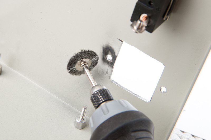
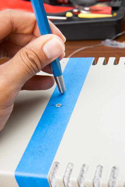
I prep one of the IEC screw holes for my safety ground.  This time, I got smart and used a wire wheel attachment on my rotary tool.  Works way faster than sandpaper.

p267390239-4.jpg
\

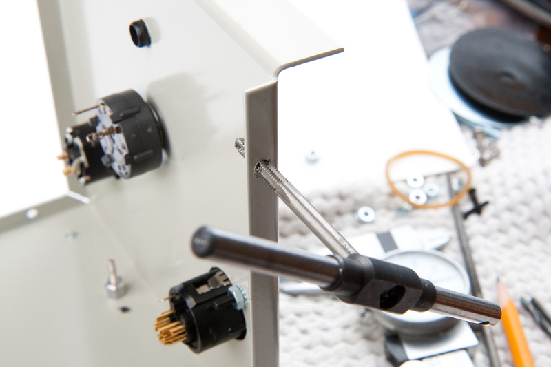
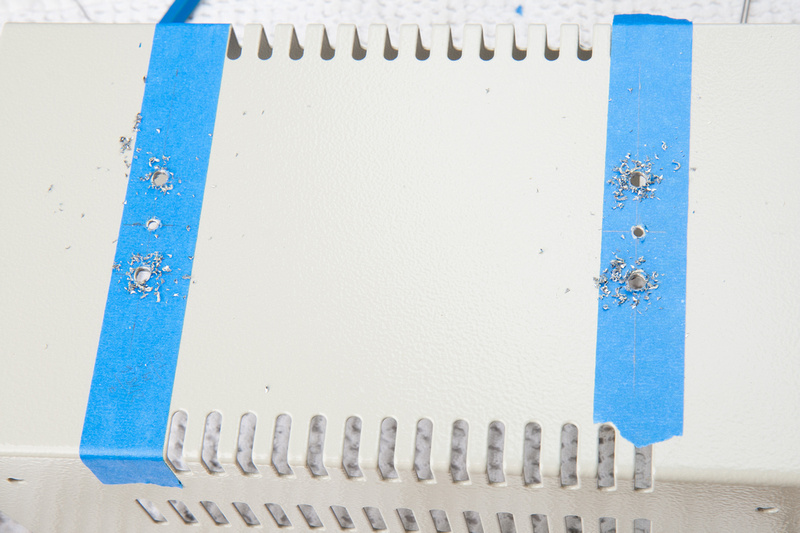
Everyone seems to complain about the thickness of the Hammond enclosure's steel. . . I haven't found it to be too problematic, but since we have thicker steel, I figured it would be a nice touch to tap the holes to mount the cover instead of using the included self-tapping screws.  I tap for 8-32.

p116429630-4.jpg


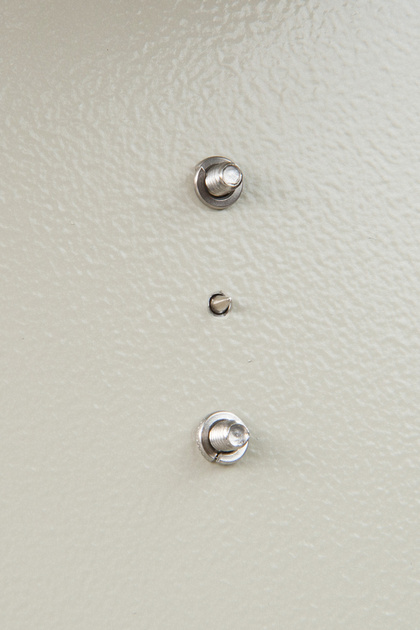
IEC mounted with a solder tab for my safety ground.

p25519937-4.jpg


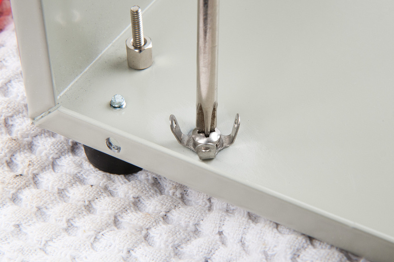
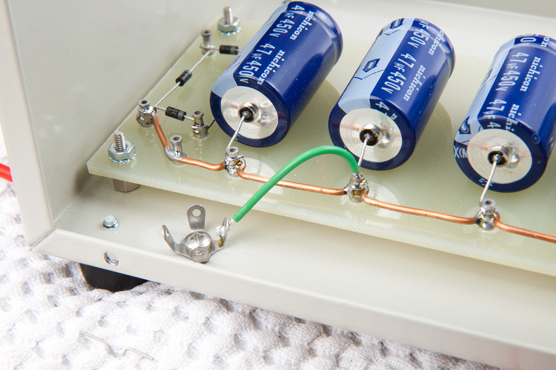
Given the number of wires I anticipate bringing to the star ground point, I add an additional solder tab there as well.

p394189238-4.jpg


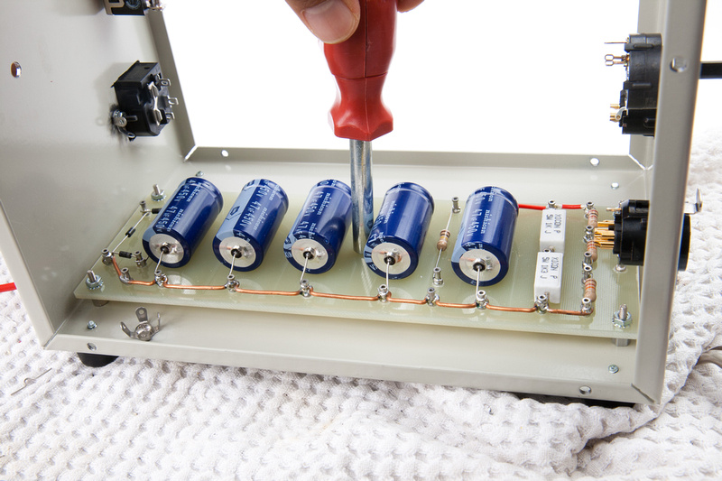
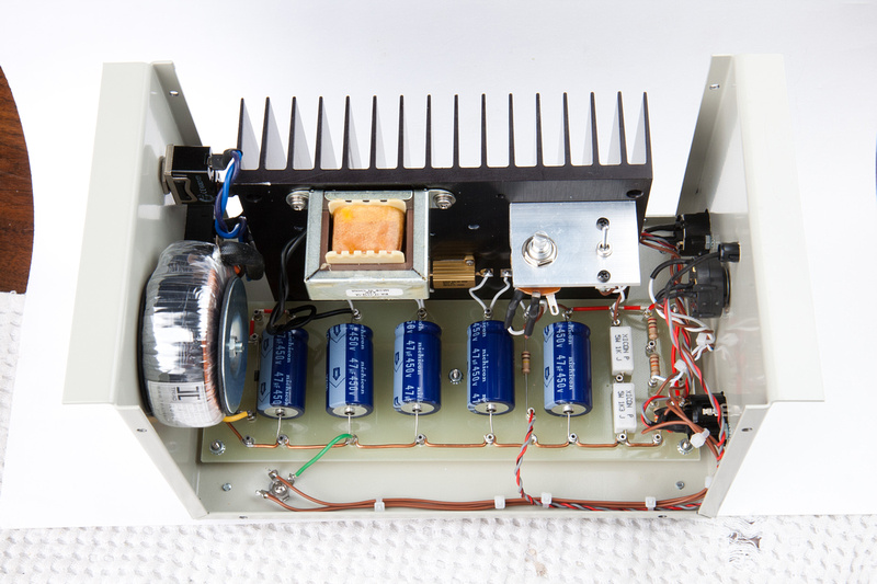
Next, I re-install the turret board hopefully for the final time.

p365160478-4.jpg


and begin my mains wiring.  I am using silver teflon wire throughout.  I have purchased various colors and gauges here and there on Ebay and have built up a small supply.

p342212822-5.jpg


turret board connects to star ground.

p53352499-4.jpg


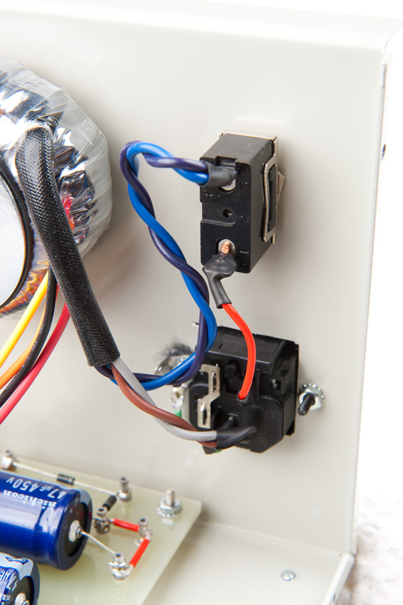
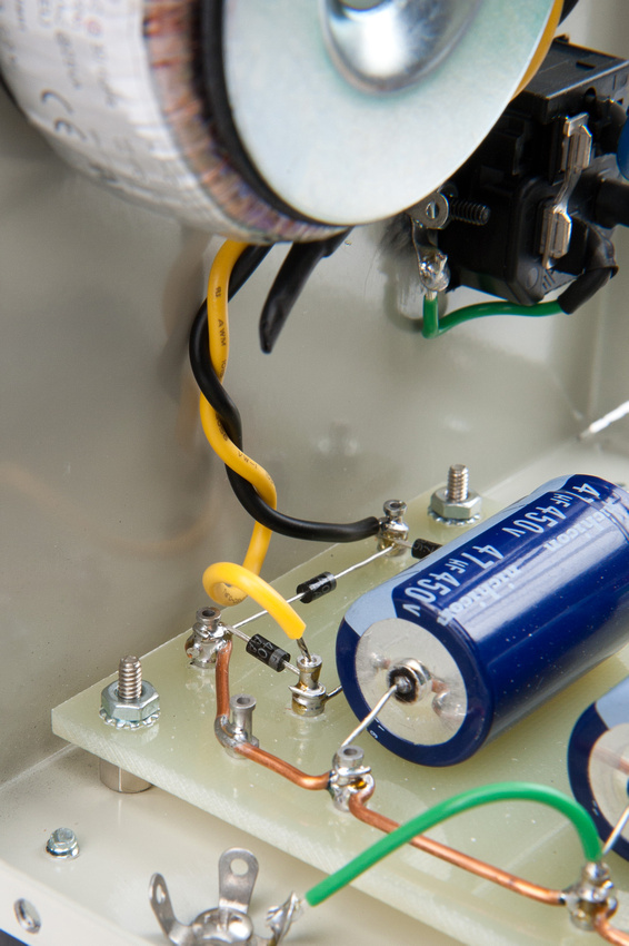
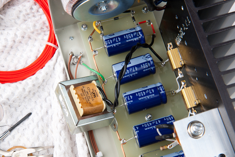
Here I re-install the toroid and wire in the primaries.  For this Triad toroid in the US (110V), I wire the primaries in parallel.

p77176786-5.jpg


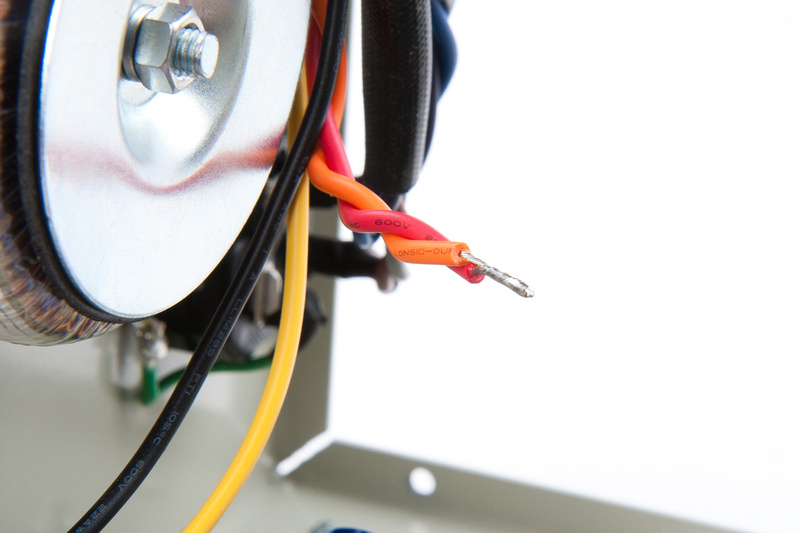
The secondaries will go in series, so these two wires are spliced together and securely covered with some shrink tubing.

p309078790-4.jpg


And the secondaries feed into the turret board here.

p520466436-5.jpg


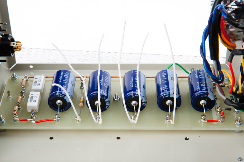
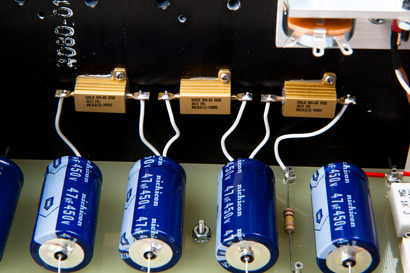
Since it will be difficult to solder along the back edge of the turret board once the heat sink is installed, I pre-install some "pigtails" to the back side turrets.  These will connect to the chassis-mount-type resistors that are already installed on the heat sink assembly.

p355820922-4.jpg


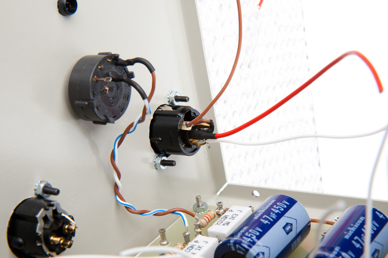
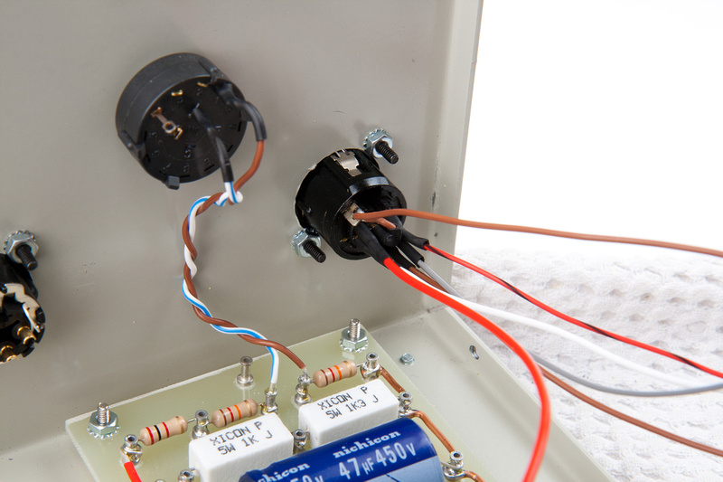
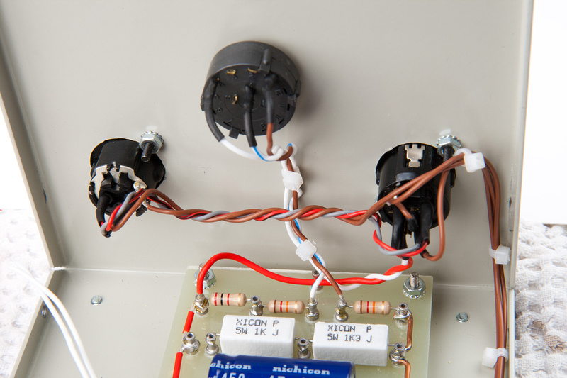
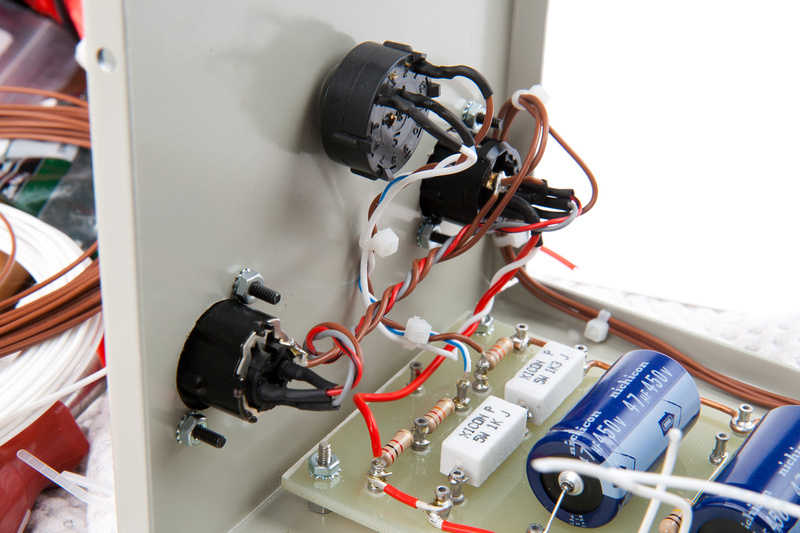
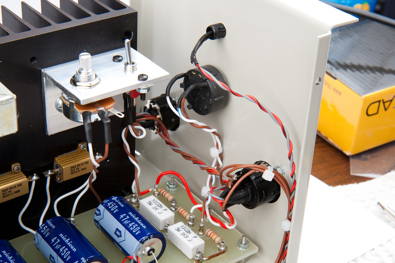
The Cardioid mode wires are installed on the pattern select switch and I begin wiring the 7 pin XLR.  Here chassis ground, +105V and +48V pattern wires are being installed.

p176851638-4.jpg


p351882528-5.jpg


Next, audio 0V, audio +, and audio - go into the 7 pin XLR.

p66826539-4.jpg


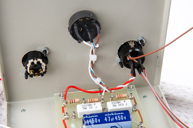
+105V and pattern are hooked into the turret board and pattern select switch.

p465978221-4.jpg


And the output 3 pin XLR is wired in.

p171184001-4.jpg


in my mind, this was going to come out a lot neater, but I guess it's not a total embarrassment.  It should be quite solid.

p211095749-4.jpg


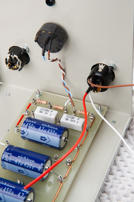
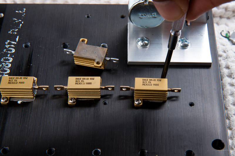
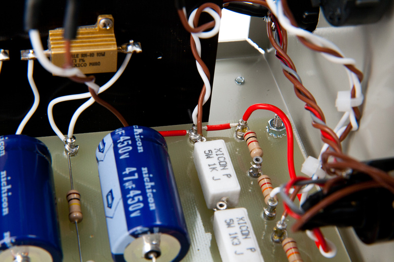
from input others have given who have used this particular toroid, I decide to change my 680R chassis mounted resistor to 1K and to change my 500R 5W pot to 1K as well.  This is what people have reported to work, and it's much easier to change the components now before final assembly than later after everything is wired in.

p188712853-4.jpg


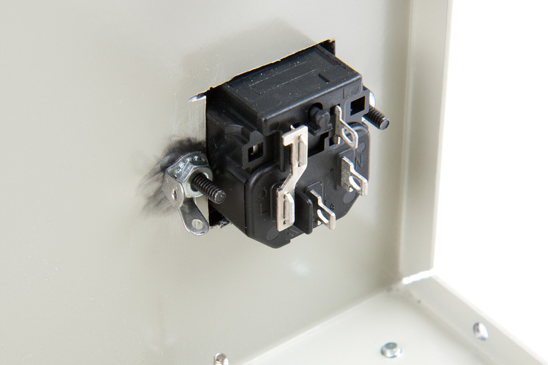
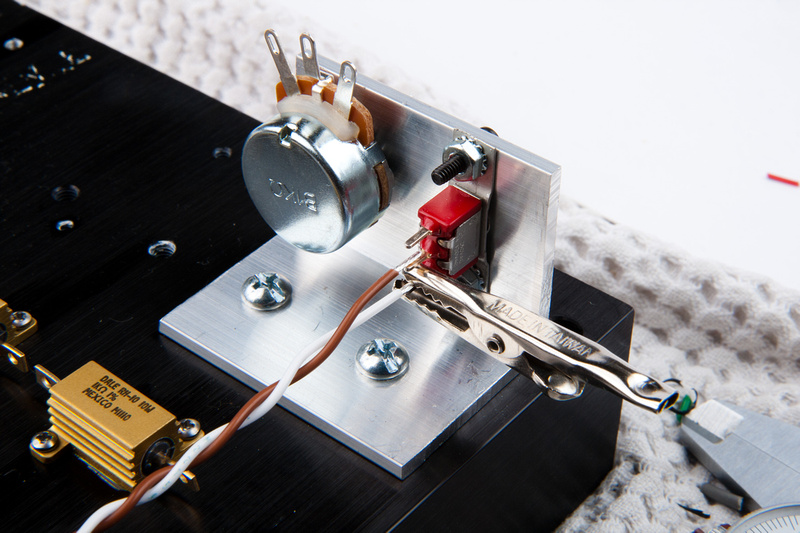
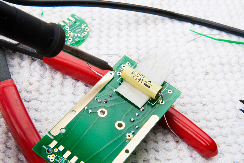
This is how I set up to solder my "hacked" test switch as it does not have solder lug holes.

p116815040-4.jpg


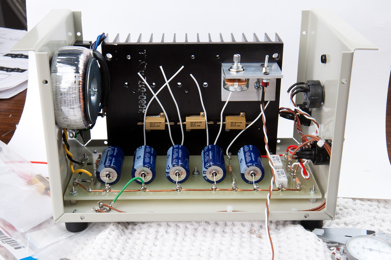
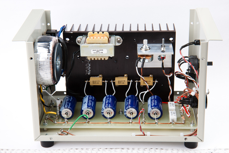
And, the heat sink assembly goes in.  Notice I have removed the choke to allow easier soldering on the chassis-mount resistors.

p488270465-4.jpg


resistors are wired in.

p78927863-4.jpg


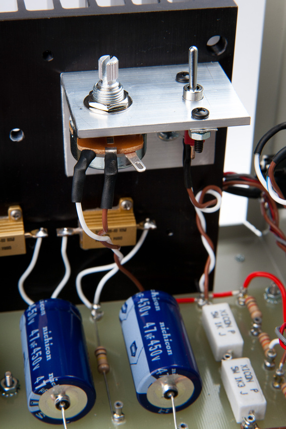
voltage trim pot and test switch are wired in.

p146553246-5.jpg


p511675073-4.jpg


and I install the choke loose first for better access to the solder points.

p411831738-4.jpg


and mount the choke.

p447011657-4.jpg


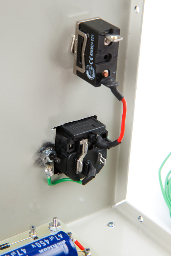
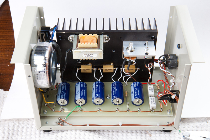
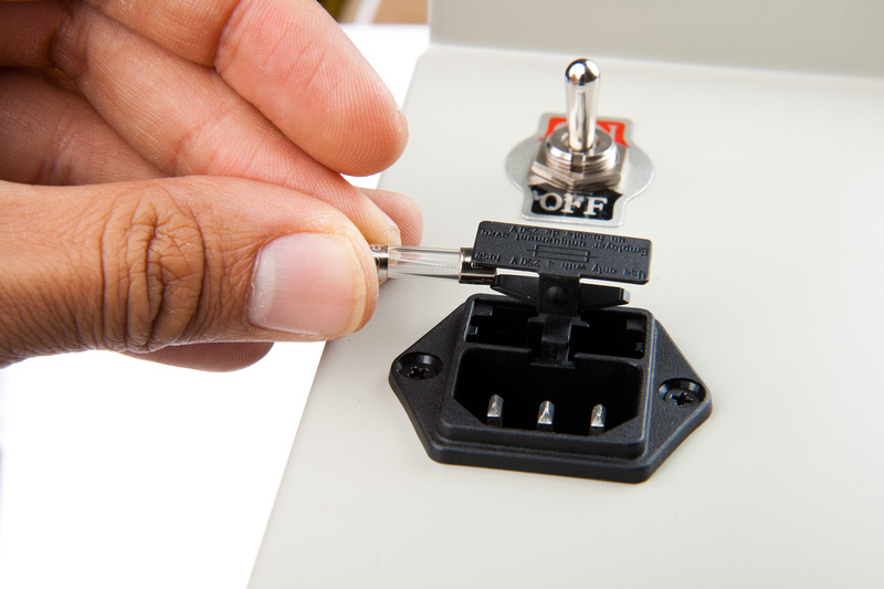
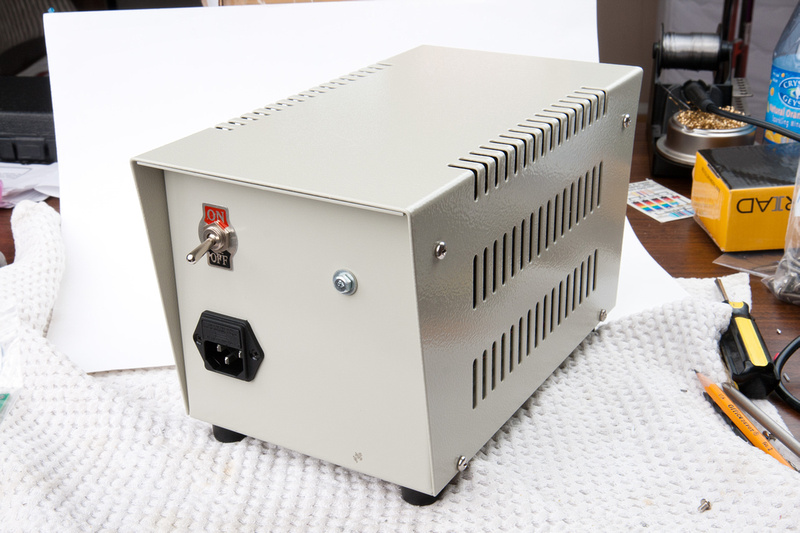
spare fuse goes in the IEC.

p61881408-4.jpg


and then main fuse.

p211827093-4.jpg


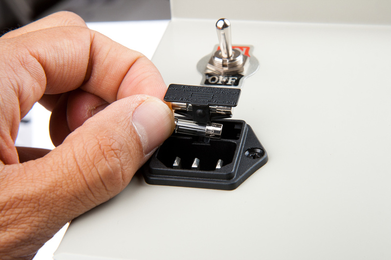
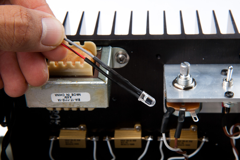
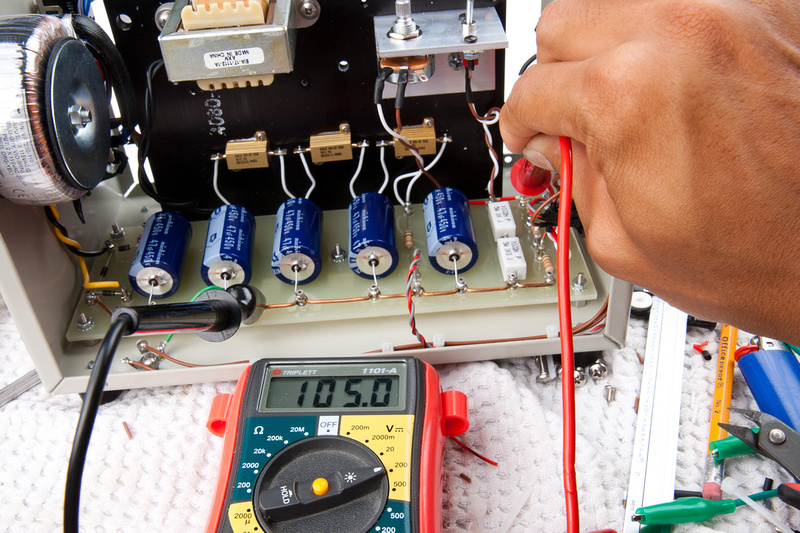
NExt, I prep my LED for installation.  Due to discussions on this thread regarding LED power consumption, prior to connecting the LED, I mearure its current draw on my DMM, and it is drawing 1.5mA which I'm happy about.  This means the LED is not sapping too much of my power.

p118918787-4.jpg


Test mode engaged, I trim out the PSU for 105V. . . spot on.  The PSU initially powered up at 116 with the pot somewhere middle-ish.

p244854132-4.jpg


Humans win!

p494854831-4.jpg


p375993431-4.jpg


p488352077-4.jpg


p87408080-4.jpg


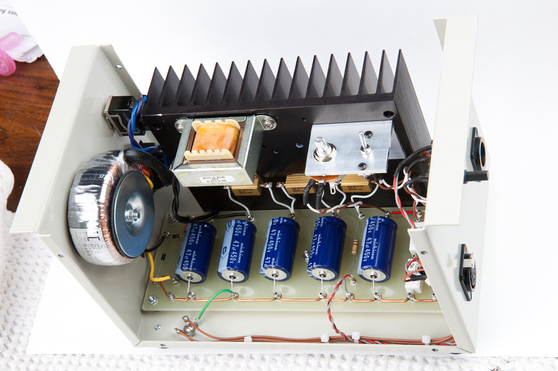
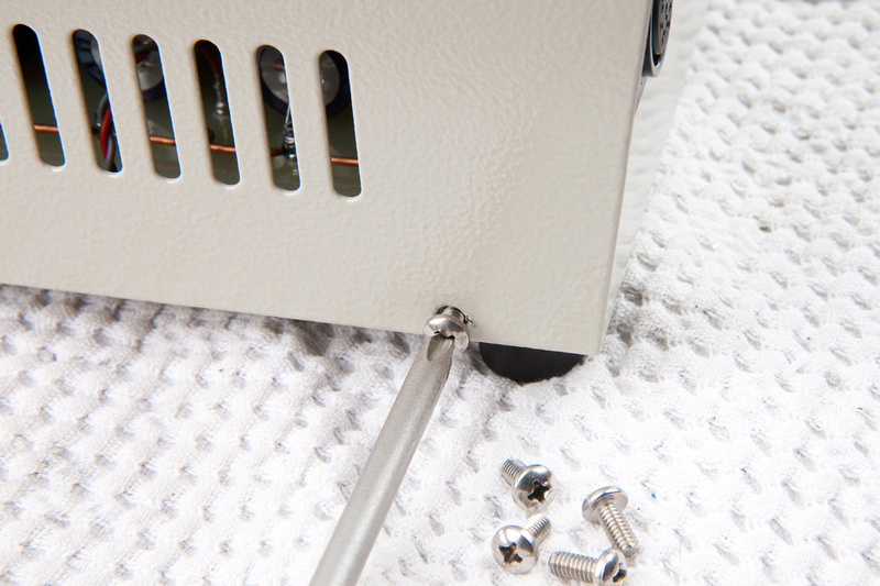
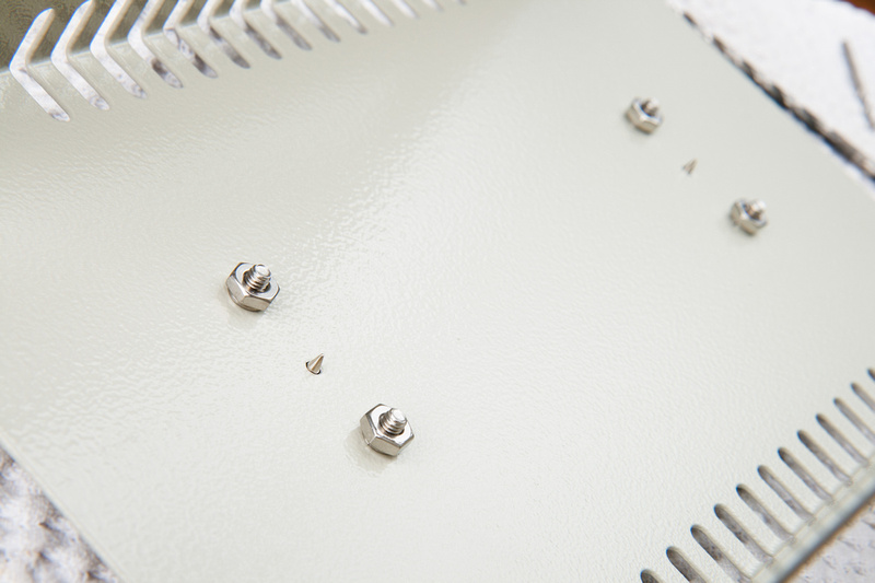
Next, I flip the test switch to "operate" mode and install the enclosure cover with some 8-32 screws.

p204894166-4.jpg


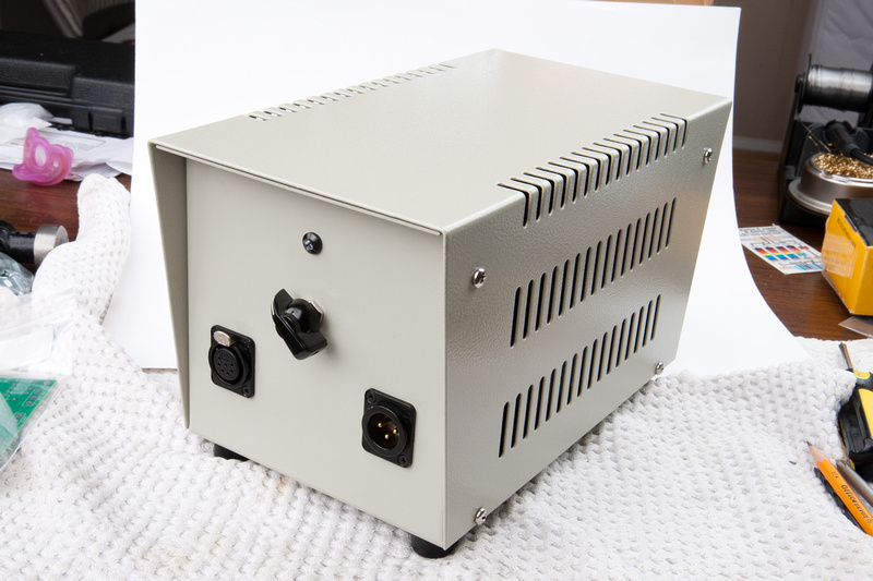
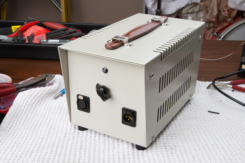
last step is to install a little chicken knob on the pattern select switch that I picked up at a local electronics store.

p536200878-4.jpg


p119011288-4.jpg


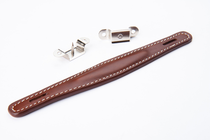
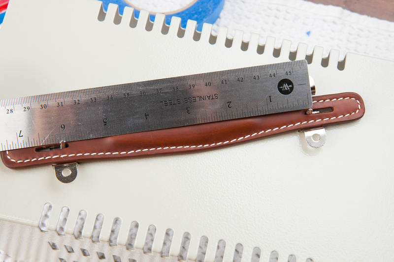
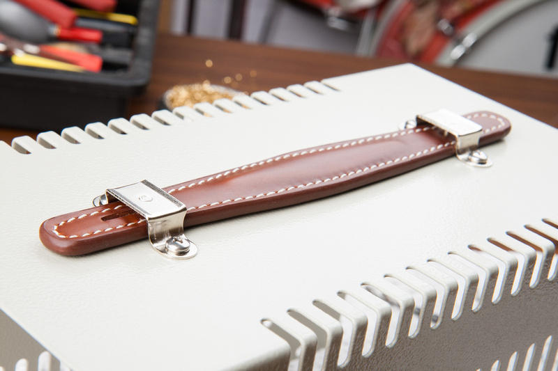
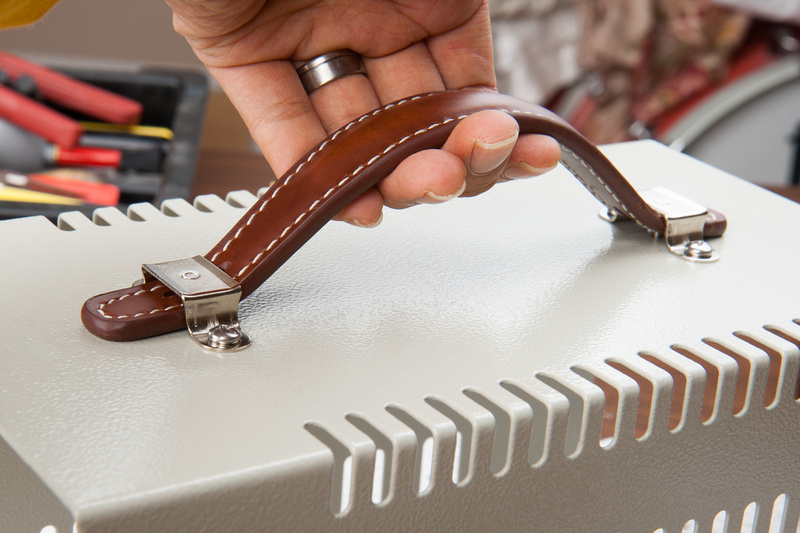
And there it is. . . a successful point to point PSU build for the MK47 microphone.  I just need to add a handle of some sort on top. . . I'll probably use a fake leather guitar amp handle of some kind from ebay.  All in all, I learned a bit.  A few Mouser orders, a few wrong parts, a little scrambling around house looking for screws and tid-bits, but in the end, I'm pretty happy with the result and feel like it should stand up to heavy use.  The test resistors do indeed get hot, but that will not be inline under normal use.  The only thing I don't really like is the trimmer pot also heats up a bit.  It is connected to a thick Aluminum L-bracket so that helps a bit, but I might think about upping the chassis-mounted resistor values as those are running VERY cool in this configuration.  Not even warm to the touch.

Next, I will look to do a PCB build as I await my donor bodies (unmarked Alctron GT-2B's) that will be inbound directly from the motherland.

This PSU was the main hurdle for me for this project as information seemed to be a bit more scattered.  Hopefully, it will be downhill from here with a little bit of luck and a steady hand.
 
mulletchuck said:
I don't understand what the internal switch was for, tho.  Where was that feature explained?
Hi,

It's explained in the schemo.It just switches the 2,3K resistor in circuit to give it a load while testing without a mic connected.This way the 105 vdc can be dialed in without killing your beloved mic,hahahaha.....after that just switch it to off.

Cheers,

Udo.
 
Thanks for the heads up.  I need to adjust the BOM to reflect changes to account for the 230V toroid as well as add miscellaneous items like the mains power switch, screws, standoffs, lock washers, and other bits.

Also, I just pulled the trigger on a large order of Alctron GT-2B donor microphones.  It looks like they will come in just in time for the next batch of mk47 kits, so if anyone is interested in a donor mic, please let me know.  I should have more than a few spares as I had to order minimum at volume directly from the factory.
 
Finally finished negotiating with Alctron on my microphone order at quantity  I requested 31x unmarked GT-2B microphones in my initial order so there should be plenty to go around if folks are interested in using this body.  Deposit has been sent so production of my batch has commenced.  I am waiting for a verification sample to ship via air in advance of the main shipment which will arrive by ship.  Once I receive the GT-2B sample, I will be able to finish out this project and photo set. . . not that the project lacks documentation from this point forward as ioaudio has made a nice build thread already.

I have also received one of Dan's beautiful psu enclosures to demonstrate a PCB based power supply build in detail.  Even though the point to point build is educational and loads of DIY fun, I suspect there will be a lot less futzing around with metal on the pre-fab'd enclosure and PCB build.
 
one more detail on the PTP PSU. . .well, this and then try to figure out how to make pretty cardioid and omni markings that look decent.

p1142863444-4.jpg


I bought this leather handle on Ebay and the quality looks pretty ok.  It's not full grain leather or anything like that, but it's not like I'm going to be wearing this, or sitting on it, or fondling it all the time :p

First, I measure the anchor distance with the handle in the stowed position.

p1142863664-4.jpg


Then, mark and drill my holes for the center lug which incidentally carries all of the weight, so I find a drill bit that is just the right size for a tight fit.

p1142864596-4.jpg


I mark my screw hole center locations.

p1142864066-4.jpg


Center punch the holes. . .

p1142864980-4.jpg


and drill.

p1142865234-4.jpg


Next, I pull some 8/32 pan head screws, nuts, and lock washers

p1142865448-4.jpg


. . . and install.

p1142865648-4.jpg


p1142865808-4.jpg


Not too shabby!

p1142865962-4.jpg


Everything seems to work as designed.  Perhaps I could have set the anchors a little bit further apart, but this will work.

p1142866232-4.jpg


And the PSU is looking all buttoned up and finished now.  I don't quite mind the plain Hammond case too much with its factory powder coating.

p1142866980-4.jpg


Beesneez has recently entered with which market with a few limited time offers on DIY parts, so I took the opportunity to order up a pair of their new M7 capsules for this build!  Ben Sneesby indicates that this is now their "go-to" premium U47 type capsule sounding in his personal opinion, better than their venerable K7 capsule, so I figured I'd give it a try. 

Also, my sample GT-2B body should be ready and shipping next week from the factory in the motherland along with another very interesting Alctron oem sample microphone.

Not much longer now until all parts are in hand to complete these mics.
 
Nice job Chunger! This is my first post here(been lurking a long time), I'm a total newb, I started modding cheapies a while back, built some SCA pre's, been studying and messing with everything!, then found the mk47 project. I wanted to do it badly, but was intimidated by the psu..., not no more;) Thanx for the awesome thread, and count me in on those mic body's. BTW, I too expect when i order something that it will arrive, your reaction to that situation was more measured and respectable than anything i could have mustered, thats for sure! Can't wait to see your new psu and mic build pics. Thanx, good luck and Peace

Ps
any idea the $ on the bodys?
 
I am quite convinced that I am not adding anything to the collective knowledge base about this project by documenting the heart of the mk47 microphone kit because ioaudio's build documentation is so thorough and detailed:

http://www.groupdiy.com/index.php?topic=41379.0

But, it does not hurt to have another look at the process.  After many delays, I finally dig out the microphone PCB and kit.

p1155024636-4.jpg


The first step is to separate the 2 PCB's.  Is use a fret cutter because that was handy in my toolbox.  I know. . . not your typical electronics DIY tool, but I'm sure any cutter will work.

p1155024914-5.jpg


Then, use a file or sand paper to clean up the perforations in the PCBs

p1155025118-4.jpg


Next, solder the remaining pins on the BV.08 transformer.  My kit arrived with 2 joints pre-soldered.

p1155025356-4.jpg


Then, I install the 30K and 100K resistors.

p1155025550-4.jpg


p1155025774-4.jpg


. . .and trim the leads.

p1155026004-4.jpg


Next, prep the diode for installation.

p1155026196-4.jpg


and install.  Make sure the orientation is correct with the solid stripe end facing the direction of the silk-screened arrow.

p1155026336-4.jpg


My previous projects did not absolutely require cleaning the solder flux off of the PCB's, but from reading through microphone modification and build threads, I am lead to believe it is beneficial to clean all of the flux residue off of the PCBs, so I am for this build.  I found that 90% concentration isopropyl alcohol works fine if I mechanically scrub the parts.

Because I will not be able to reach some of these joints after parts are installed on top of them, I clean the PCB now.

p1158768886-4.jpg


It takes a bit of bending to get the 1uF capacitor into position.

p1158769828-4.jpg


I didn't know if I needed to keep the body body of the 1uF capacitor off of the PCB, but I used a paper spacer to float it off of the solder joints underneath it.

p1158769246-4.jpg


Next, the 27R resistor goes in.

p1158769828-4.jpg


The excess leads need to be trimmed flush to the PCB behind the relay.  My cutters do a decent job of it.

p1158770574-4.jpg


. . .and, why not?  Another round of cleaning with isopropyl alcohol.

p1158770810-4.jpg


Next, I trim the mounting bracket off of the large capacitor.

p1158771208-4.jpg


. . . and pinch the leads so they will fit into the PCB solder lugs.

p1158771388-4.jpg


Install the capacitor and secure with the provided zip tie.

p1158771614-4.jpg


p1158771914-4.jpg


Next, position the relay.

p1158772424-4.jpg


And solder the 2 lugs in place.

p1158772188-4.jpg


The build instructions indicate that glue should be used to secure the other end of the relay so I bought some of this from an auto supply store.

p1158772652-5.jpg


and apply some of it under the relay.

p1158773038-4.jpg


Latest posts

Back
Top