Official 33609 builder's tread. See 1st page for updates.

GroupDIY Audio Forum

Help Support GroupDIY Audio Forum:

This site may earn a commission from merchant affiliate links, including eBay, Amazon, and others.
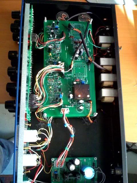
C1 and C2 on the top row are unlabelled. Are they 470uF?
C13 on the bottom row is unlabelled. Is it 10uF?
The thing labeled "J" in the bottom right hand corner, is this a jumper?
What is the value of the trimpot R3 on the PSU board?
Hi!
C1 and C2 are 470uF 10-25V, pitch 3.5 or 5mm, diameter up to 10mm audio quality 'lythic caps.
C13 tantallum 'lythic cap 10uF 16-35v pitch 3.5mm
J in the bottom right hand corner is a jumper, right.
Don't use trimpot on PS PCB, there's resistor 3k57..
with 196R it gives exactly 24v.

The capacitor to the left of C14 on the main board which is unlabelled, is this C15?
Yes.

There is a space for a 3.5 x 8 mm electrolytic above CJ1 on the main board, what is this for?
If you're using DOA like JE-990...actually, just dead option anyone likes here.

And looking at the 33609 manual, it looks like R10' (on the compressor recovery switch) should be 24K, not 6K8?
I used older manual.
Checked now, according orig. Neve, (ek20236) it is 6k8...
according to new ver. of 33609JD manual, PL20235, it is yes, 24k!!!
See:
http://i251.photobucket.com/albums/gg291/diy33609/compREC_sw.jpg
But on lim recovery, it is 6k8 on both manuals.
http://i251.photobucket.com/albums/gg291/diy33609/limitREC_sw.jpg
Really, dunno...with 6k8, it sounds a way fast, but not bad on drums...
Cant't say it is 25mS anyway...
Igor did you match the diodes you sent out, or does that need to be done, or is it not necessary ?
Yes, we matched diodes for 5 groups Vff, so worth case is less than
1% tolerance.
While maeasuring them, try to keep same temperature, because if your room temp is 22deg, and fingers 36 deg, it can affect results.
 
Thanks Igor.

Here is a European BOM with Farnell order codes. Caps are Wima polys, Panasonic & Rubycon lytics. BOM is everything you need for 2 channels, hopefully...

BOM

Richard
 
Hey Richard-

I just noticed that you have the incorrect value for the PSU C1 Cap:

1198551 C1 (PSU) = 6800uF 50v but it's supposed to be a 4700uF 50v.

Thanks for posting your BOM!

-Josh
 
[quote author="JdJ"]Hey Richard-

I just noticed that you have the incorrect value for the PSU C1 Cap:

1198551 C1 (PSU) = 6800uF 50v but it's supposed to be a 4700uF 50v.

Thanks for posting your BOM!

-Josh[/quote]

Hi Josh -- quite right, I forgot about that. I generally go for the largest cap I can physically fit on the board after the rectifier :grin: Should probably have changed it back to the specified value before posting the BOM though... will fix that.

Richard
 
Anyone know the value of RZ on the top right hand side of the main board?

There's no value marked on Igor's BOM and I haven't spotted any reference to it in this thread...

Presumably it's value depends on some other components :?:
 
hi guys,

i´m bit confused about the output transformers. i want to buy at aml.
which one would you prefer?

ca-18-vtb 1847
ca-18-vtb 9057
ca-18-vtb 1148
ca-18-vtb 9049


thx

lars
 
I got the LO1173 equivelent - vtb9056. It's not on the site I don't think but if you email Colin he'll help you out.

Peace

Jim
 
I have a silly ? i have finished the unit except I forgot to get the relays I should just be able to jumper it so I can begin to setup the unit this should not effect the setup later when I put the relays in since it's just the ins and outs going through the relays right ?

Thanks
 
Hi, if you used 12v relays, put 12v jumper to connect relays in series, if 24v relays used, put two jumpers marked 24v for parallel connection.

Jumpers are located on top side of pcb beetween relays, they looks as smd pads.
 
Hi,

i´m finishing my neve :cool:

now i got my transformers, but i do not know how i can connect it. i do not find any technical data of it. can someone help me?


CA-18-VTB9056_composite_600.jpg


...another question, does the transformer need any termination?

thx lars
 
THAT'S DAMN COOL!!!!!
Guy who not talking much as most of....you know ;)
Impressing!!!!

IMHO better to use shielded wires for 8-and 12- pin connectors,
see:

http://i251.photobucket.com/albums/gg291/diy33609/CABLES.gif


but think the leakage from sidechain to audio is negligible.

I very happy to see this picture. Just great!
 
And here is my baby :green:


inside.jpg
totale.jpg


knobs.jpg
meter.jpg


Everything works very well. Thx to all those lovely people out there.
Big Kiss to Igor :thumb:, and the fast guys form Audio Maintenance.

Greetings from Lars Cologne Germany
 

Latest posts

Back
Top