PASSIVE RELAY-BASED CONTROLL ROOM KITS BUILD/SUPPORT TREAD

GroupDIY Audio Forum

Help Support GroupDIY Audio Forum:

This site may earn a commission from merchant affiliate links, including eBay, Amazon, and others.
Hy Igor

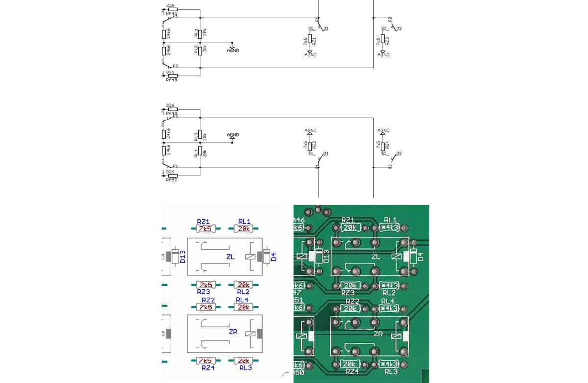
The value for RZ1...4 on the pcb says 20k and something like *4k3 for RL1...4.
However, according to the schematic aswell as the overlay you posted, RZ1...4 should be 7k5 and RL1...4 20k.

Can you tell me what the correct values are?

Thanks, Mike
 
Hi Guys,

I'm making my own front panel for this,

I was wondering when cutting out the 10mm holes for the switches to pop though how much clearance i should give? .2mm enough?

all the best

Pete

 
The value for RZ1...4 on the pcb says 20k and something like *4k3 for RL1...4.
However, according to the schematic aswell as the overlay you posted, RZ1...4 should be 7k5 and RL1...4 20k.

Can you tell me what the correct values are?

Depends on your speaker's impedance.
For most cases, 7k5 is fine. 4k3 used for 20k input impedance speakers (amplifiers, to be correct).
Most speakers have 10k input impedance, use 7k5. This does not affects sound, worst case it
will add error to 1db steps (say, instead of -25 db there will be -24.5 or -25.5...not critical
untill it is not very high precision mastering room).
 
Thanks Igor, I presume you are answering about RL1 on the PCB. But there is a question about two values, actually, difference between schematics, silk picture and real PCB. Can you please elaborate which of these to follow ?
igorCustom.jpg
 
OOPS... Now I see. My mistake. I just took older files for schematic and BOM..
RL 4k3 shown on PCB is right value, except your speaker's (amp) input impedance lower than 10k.
99% of active speaker's amps have 10 or 20 k input impedance.
Attenuator calculated for 3k.
4k3 in parallel with 10k gives 3k.
DIP3 switch SW2 used to equalize speaker's impedance.
RZ values shown on PCB are correct values as well.
If SPK2 for example has 20k imp., ZL and ZR relays switched ON by setting switch SW2.
Just take a look on schematic.
In 99% cases, EXCEPT you need very precision level steps, exactly 1db,
it is not necessary to mess with it, even possible not to install ZL and ZR relays.
 
Hi Igor,
nice work!
would i be correct in thinking that it would be fairly straightforward to mod this to be a 5.1 surround controller?
Theres enough ins and outs.

best
paul
 
Hi Paul, this controller is made for stereo, but you can stack 3 audio boards.
If you don't need separate controll for front/rear speakers, it is OK.
 
Hey igor,

I remember you mentioned about moding it for 3-4 outputs. I don´t need 4 inputs, just two is enought, but at least 3 audio outputs is a must.
Please can you post how to do that?

Thanks!

Synthi
 
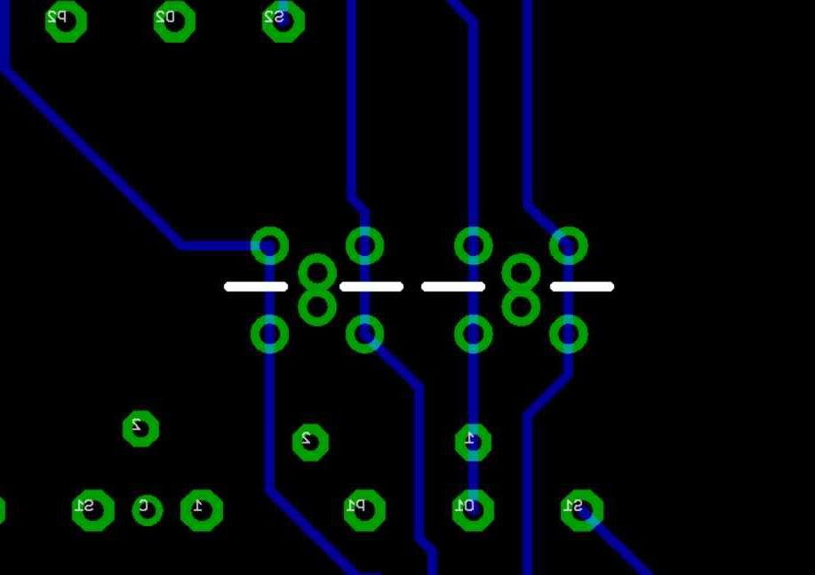
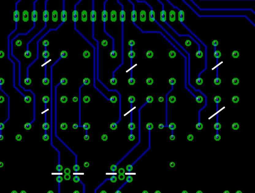
All we need to do is reverse inputs and outputs, cut connections to ground on outputs,
remove 75R resistors on outputs.
Refer to schematic. Output relays are connected to ground when output is muted.
Remove R 3,4,5,6,7,8.
Cut bottom layer traces as shown on pictures (white lines).
Reverse input and output with shielded cable, no need to use Monster diameter 12mm,
use something like Mogami line level cable.
Write IN 1,2 instead of MON1,2 on controller.
Write OUT1,2,3,4, instead of IN1,2,3,4 on controller.

SUB can be used as monitor output now (out to meter/phones without level,
paralleled to CRM source of input selector).
Previous METER output comes after level now.

Termination switch (DIP-3), relays ZL and ZR are useless as well, remove it and install
proper terminations on speaker outputs itselves if needed.
Logic is next: attenuator's load should be 3k, and it is allready terminated with 4k3 (RL1....4).

Hope everything is clear.

inp_mod.jpg


out_mod.jpg

 
Hi Igor,

My Hafler Amp has 47K input impedance per phase, is that going to be a problem for the values of RL and RZ?

cheers!

Pete
 
Nope. Install 4x approx. 36k resistors in parallel to amp's input, between - and gnd, + and gnd.
All this  termination stuff dos not affects the sound, only precision of level steps.
 
Hi Igor,

All fired up working first time! works lovely jubly!

One question, Can i use Unballanced inputs? would that casue any problems grounding out the negative to ground on one of the inputs?

Best
Pete


sinestaraudio said:
Hi Igor,

All fired up working first time! works lovely jubly!

One question, Can i use Unballanced inputs? would that casue any problems grounding out the negative to ground on one of the inputs?

Best
Pete

Hi Pete,

Just wondering -  what have you done for cases on this project? 

Obviously the 1RU case for the audio stuff is straightforward, but have you gone for a desktop case for the controller side?

If so, do you mind sharing which case you've gone for?  I'm struggling to find a sloping top case that's appropriate for this...

Cheers,

Rob

 
Hi Rob,

I have made my own with Front Panel Express, Im happy to share this with you if you like.

It should turn up tomorrow, ill post pics once its here, Lets hope it all fits!!

I have opted for a 4u case, as it will house my M&S Matrix / and Width contols plus a 2 channel MIxer for paralell work.

Best

Pete

 
So you're incorporating everything into one single case?  I'm considering this option too.

Looking forward to the pics!
 
Hi Pete, I don't think there can be prob with unbalanced outputs.
I using same controll room system more than 2 years at my home setup.

Pictures please!!!!
 
Back
Top