Poor Man's Tube Mixer

GroupDIY Audio Forum

Help Support GroupDIY Audio Forum:

This site may earn a commission from merchant affiliate links, including eBay, Amazon, and others.
ruffrecords said:
I made all the spare protoype main PCBs available here at cost. I have one left if you are interestedThere are lots of transformer options.

Lastly, you should know that I am not proceeding any further with those particular PCB designs. As I have said in an earlier post, the sheer volume of wiring between the main board and the two panels makes them impractical and very difficult to service. This has caused me to re-evaluate the method of interconnect and revert to the motherboard method I use in the EZTubeMixer project.  I have also been disussing the project with several potential customers whose input has been invaluable. This has cause me to revisit the overall design several times in an attempt to reduce cost yet retain flexibility. The schematic posted above is the latest attempt.


Cheers

Ian


Is the drawing in the beginning of this thread relevant to the prototype board? the MiniMixer drawing?
 
scott2000 said:
Is the drawing in the beginning of this thread relevant to the prototype board? the MiniMixer drawing?
Not any more. The design has gone through several iterations since then generally getting simpler each time.

Xheers

Ian
 
ruffrecords said:
Not any more. The design has gone through several iterations since then generally getting simpler each time.

Xheers

Ian
Thanks..I'm following that...... I was just referring to the original prototype boards that were the first run.... is there a drawing that is more or less relevant to them?
 
scott2000 said:
Thanks..I'm following that...... I was just referring to the original prototype boards that were the first run.... is there a drawing that is more or less relevant to them?

Hi Scott,

I have been through the entire thread and it is now clear to me that I never posted the actual schematic of the prototype main board (although it was described in detail). Any way, to put that right I have attached it to this post. The only different between this schematic and the actual prototype PCBs is that the mic pre relays have been ditched and replaced with regular toggle switches. The main PCB use seven tubes.

The very latest version of the design (not yet in PCB form) first changes the left and right buses to balanced ones, then feeds the DB25 inputs direct to these buses (thus eliminating two tubes), the mic pre pan pots are changed to LCR types and also feed the balanced bus and lastly the transformer balanced line inputs at the bottom no longer need input transformers because the bus is balanced thus saving two transformers.

Cheers

Ian
 

Attachments

  • MiniMixerLight-3.pdf
    45.7 KB
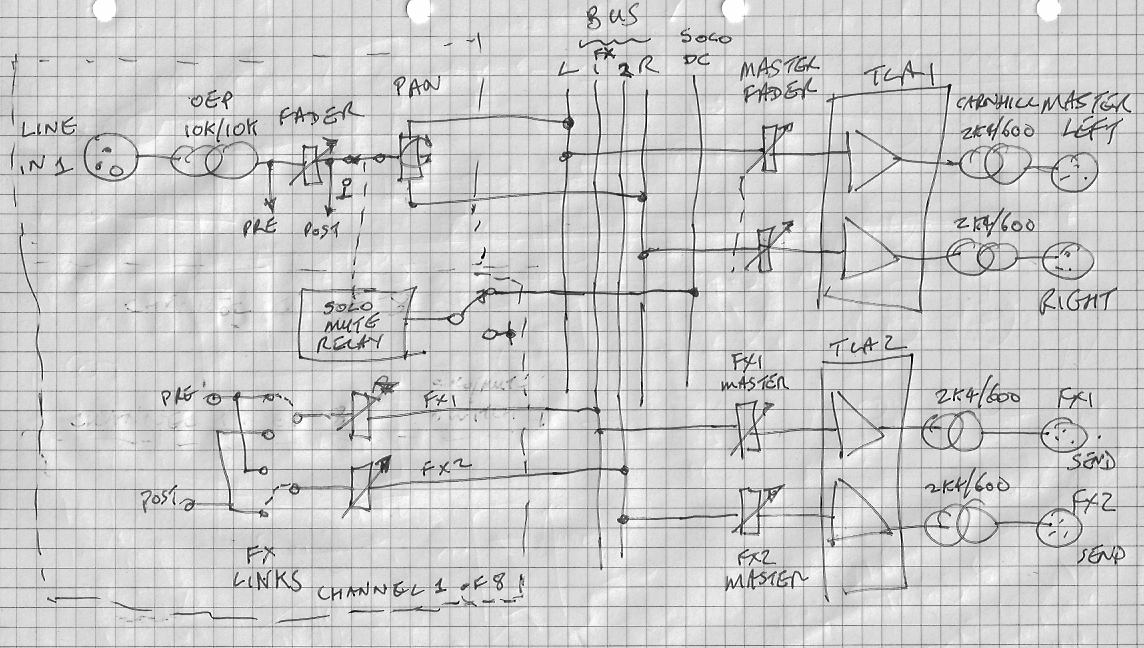
I do not wish to confuse people but the latest mechanical design will use good old EZTubeMixer plug in modules. This means you only need to build the boards you use rather than partially populate one huge PCB. One advantage of this is that completely different alternative mixers become possible. I have recently been talking to a prospective customer about a line input only version with AUX sends and pan on every channel. It turns out you can pretty much do this passively with just a pair of tube based bus amps (3 tubes max). The block diagram of the final version looked like this:

basicplus-FX.jpg


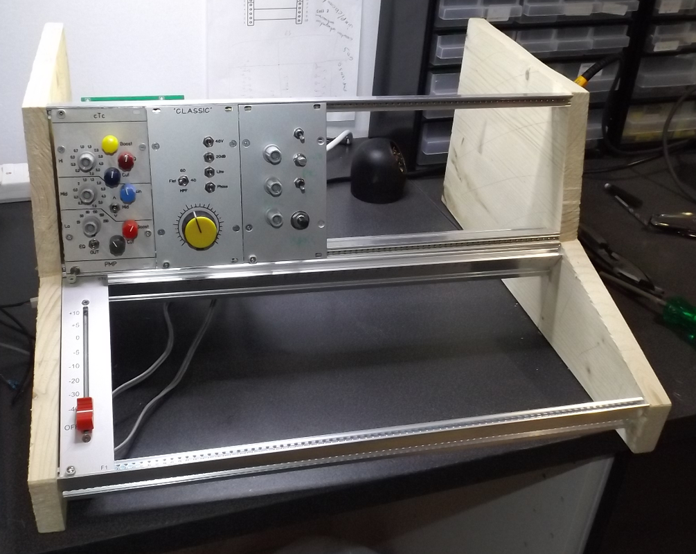
The design uses a very low cost OEP 10K:10K input transformer per channel and a couple of TLAs for bus amps for a total of 6 tubes. At a push these could be replaced by a pair of Classics for a reduced tube count of 4. Using the new mechanical design (roughly this one):

PMTMlashup.png


You could built an 8 line input version of this for about £2K all up.

Cheers

Ian
 
One more question regarding the original prototype boards and drawing.  Are the MU stages considered to be your Tube Gain Make Up circuit mentioned here? With the drawing attached in the first post?

https://groupdiy.com/index.php?topic=43973.20

Or something else. ? Sorry if I missed it....

 
scott2000 said:
One more question regarding the original prototype boards and drawing.  Are the MU stages considered to be your Tube Gain Make Up circuit mentioned here? With the drawing attached in the first post?

https://groupdiy.com/index.php?topic=43973.20

Or something else. ? Sorry if I missed it....

It is the same basic topology but instead of the 6CG7 I now use a 6922 tube. This has a lower plate resistance and, via a 2K4:600 transformer will drive +20dBu into a 600 ohm load. There is also a couple of dB increase in gain. This version was first used in the Classic Solo project.

Edit: Here is a link to the Classic Solo document which includes a schematic:

https://drive.google.com/file/d/0B_n67A1hN3qtUWhWUjVoOXVxU28/view?usp=sharing

Cheers

Ian
 
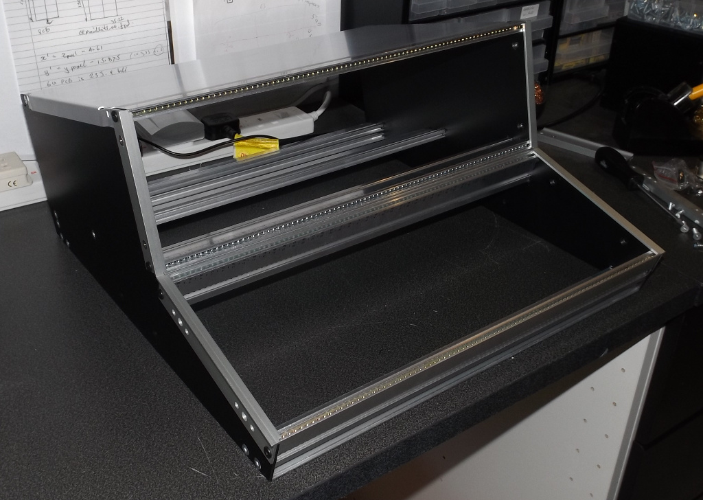
Today I received the new custom designed metalwork for the poor man's tube mixer. This now has a proper 3U space for modules and backplane plus a sloping front 4U section for faders and misc controls:

PMTMchassis.jpg


I fitted it with a few old EZTubeMixer modules and a fader just to give you an idea of what could be built with it:

PMTMpartfilled.jpg


Cheers

Ian
 
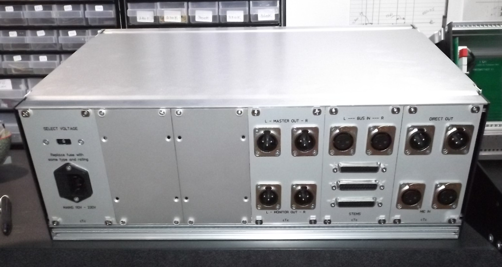
I got the panels from the new low cost UK supplier I recently found. here's how they look fitted in the back of the mixer:

PMTMbasicrear.jpg


The pair of mic inputs with their direct outs is on the right. Next are the 24 line level balanced stem inputs on DB25 connectors plus the bus expansion inputs. The third panel has the main and monitor outputs. Far left is the mains input panel with voltage selector switch and fused/filtered IEC inlet. You can see there are two blank panels. This would typically be replaced by addition pairs of mic pre inputs meaning that fully loaded you could make a 6  mic + 24 line into 2 bus tube mixer. Alternatively you could fit sets of line inputs each with its own level and pan controls.

Cheers

Ian
 
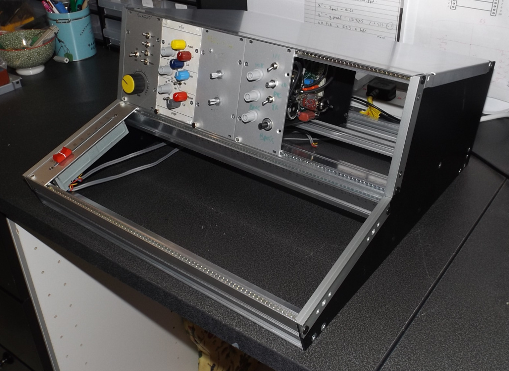
I have just finished a mock up mechanical build of the basic Poor Man's Tube Mixer (pic attached). When I first started putting it together the basic build had a very sparse front panel and fader section so I decided to add four line inputs with pan and fader in addition to the two mic inputs. There are also 24 stems coming in on 3 x db25 connectors plus a couple of bus expansion inputs for a total of 32 inputs.

From left to right you have two tube mic pres with the usual switches, a HPF and gain and pan pots. The four line input with pan pots (a HPF might also be possible). These six inputs all have their own faders. Next is the bus master currently with two faders but normally you would just have the one stereo fader. The we have the stems trim that adjusts the overall level of the 24 stems reaching the bus with a monitor level control above which feeds a separate monitor output (the stems trim would have been a fader if I could find an affordable 500 ohm one.) The last module houses the power supply. This base level version needs a minimum of four transformers (two for the mic pres and two for the bus amp). Output transformers are optional. The space to the right of the faders is pre to fit whatever you wish. I still looks like a £2000 BOM is possible.

Cheers

Ian
 

Attachments

  • PMTMmechbuildscaled.jpg
    PMTMmechbuildscaled.jpg
    191.6 KB
Ooops, correction, it currently looks like  BOM cost of £1400 is possible which means if I was building one it would have a selling price of £2100.

Cheers

Ian
 
Hello Ian

I have been reading through all the documentation you have so kindly shared on your DIY section of Ruff records and also here on the forum, so helpful, thanks.

The prospective client you name wanting a line mixer with Aux sends is roughly along the lines of something i have been thinking about but simpler, i want to run my modular synths and drum machines through it, but also feed Stems too later on.

I drew up a rough schematic. 2 TLA's for a master and Aux/master configured as Low Cost Tube Channel Mic Pres with variable gain and pad,  What do you think? 

Cheers
Ben
 

Attachments

  • Tube Mixer 1.0.pdf
    25.9 KB
HI Ben,

I think you have somehow managed to combine aspects of two different mixing methods. Your buses are balanced but you  have input transformers which will allow you to unbalance the inputs and simply the mixing circuits. Here is the sketch I drew of the line mixer with Auxes (called FX sends in this sketch):

basicplus-FX.jpg


Once past the input transformer, the signal is unbalanced and you can use regular faders and pan pots rather than the more complex switching you have to do with balanced passive mixers. You also get a master fader for free.

In your schematic it looks like you are using Auxes differently; a channel can either be assigned to a stereo stems bus or a stereo Aux bus. Either way can be achieved with essentially the same basic circuit. And you are correct, all you need is two TLAs.

Cheers

ian
 
Hello Ian

Ok, it's obvious i am kind of clueless, but willing, thanks for looking, i did some more reading and drew another schematic.

Better?

Cheers
Ben
 

Attachments

  • Tube mixer1.1.pdf
    25.8 KB
Tom snich said:
Hello Ian

Ok, it's obvious i am kind of clueless, but willing, thanks for looking, i did some more reading and drew another schematic.

Better?

Cheers
Ben
That is much better. Just a couple of tweaks and it should be spot on.

First you do not need the 200 ohm bus slugging resistor - that is only used with the DB25 board and balanced passive mixing.

And second, you should change the 10K bus resistors to 47K to reduce the loading of the buses on the channel pan and aux send pots.

Lastly I am not quite sure what you are trying to achieve with the switches attached to the pan pots.

Cheers

Ian
 
Hello Ian

Ok i have changed the values and fixed the pan pot.
I am thinking that the TLAs will be configured as Low cost mic pres with Sowter 9610 Transformers with stereo 47k rev log Gain pots, am i thinking right?
And i read further back in the thread that a 10 db pad could be a nice thing to have, which i added.
The Vu meters will have a buffered meter driver like the JLM ones. 

Cheers
Ben
 

Attachments

  • Tube mixer1.2.pdf
    46.3 KB
Tom snich said:
Hello Ian

Ok i have changed the values and fixed the pan pot.
I am thinking that the TLAs will be configured as Low cost mic pres with Sowter 9610 Transformers with stereo 47k rev log Gain pots, am i thinking right?
And i read further back in the thread that a 10 db pad could be a nice thing to have, which i added.
The Vu meters will have a buffered meter driver like the JLM ones. 

Cheers
Ben

Nearly there. Because you have input transformers you now have easier to implement routing, pan and unbalanced mixing. So you do not need the 9610 mic input transformer at the front of the TLAs. You just go straight in and save a lot of money too.

As you now have 10K master faders you do not need so much range on the gain trim control of each TLA. Normally this trim control is a preset pot on the PCB that you set once for unity gain through the mixer (it basically compensates for the unbalanced passive mixing loss). If you arrange it so this is wheen the master faders are 10dB down then you have the extra 10dB gain you may need to compensate for when you use the 10dB output pad. This will allow you to drive the TLA output stage and its transformer up to 10dB harder and thereby produce more tube tone.

Cheers

Ian

 
Hello Ian

Right i am getting a handle on this now, this mixers getting cheaper, not more expensive!

I will use 10KB trim pots for gain trimming like you have described in the TLA documentation.
 
Could you recommend a power transformer (I live in Sweden 230vac) for the 2 slot motherboard i only need 30 mA of HT Current, like the one you used in the classic standalone maybe? Sowter M002, M006 or M020 these have the 12 v för heater supply which I also need 12v - 30v dc for my Vu meter driver.
I understand that tube amps are dangerous i have worked a bit on my own ones and know people who can help.

Cheers
Ben


Attachments

  • Tube mixer 1.3.pdf
    29.3 KB
Back
Top