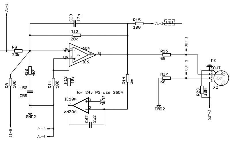
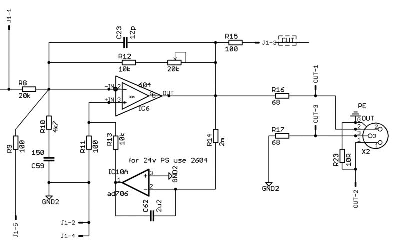
1. how do i have to solder the XLR boards??? what i see on the pictures is PS to filter board, and PS 2 to
power board, is that right??? so i just have to follow the numbers from 1 to 4, right???
I cant see it so clear,
Just connect PSU board to PS, and go from PS2 to Filter board. For making sure the + to - follow the traces on the board.
2.i have to solder XLR board ground to GRD on the power board, and add the the input ground on the plug, right???
If you take a closer look under the summing board, you will see that there are two different plane grounds, one for the XLR's that has to be connected to your star ground, and the other that is connected to your PSU ground.
Do a star ground hooked to the chassis with a steardy knut and a screw, and it's better to take out the paint where you connect this star ground, powder coating can make a bad contact, and here you will connect the IEC Ground, the PSU ground, and the Audio (XLR) Gnd.
3. how do i have to solder the toroid to a ON/OFF switch???, just the AB wires
First make sure this and that you're using the toroid the right way:
http://www.diyfactory.com/data/transformer_connections.gif
Normally you would like to cut the Phase ( L in the file above) of the Main IEC. Some like to cut both neutral and Phase.
Meaning you have 3 points on the back of your IEC, one that must be the neutral, one that must be GND (Goes to Star Gnd), and the Phase that is connected to your fuse if you have a fuse inlet IEC Socket? Check wich is wich.
From the phase you go to your switch, and from there you connect the phase of your toroid.
The neutral of the toroid goes to Neutral of the IEC Socket.
This is for if your IEC socket has the fuse inside, if not then you have to connect the Phase from the IEC socket to the fuse socket (has two solder hears for that) and from the fuse socket to the switch etc...
All this means you cut the primary section not the secondarys of your transformer, you said AB, but that is the connections of the secondary "Center Tap" to the PSU board, be carefull.
You understand that when the primary is feeded, then you have power on secondary, so if you cut secondary, then that means main power always on and toroidal always feeded

...
IF you still feel lost, then look at some pictures here and there, you'll get the point.
ANd Last but not least, don't fit any of the IC's and no DOA's, until all voltages are checked at all MAJOR points.
I personnaly like to start by checking the PSU first, and there you can check if your switch wiring is ok for you in example and you wire to main boards after checking if the PSU outputs are correct and at the right points.
Hope this helps???
EDIT: Make sure the switch you use handles 250V and more than 1A, don't use tiny dc switches for that purpose, maybe that you knew, but better be safe than sorry...


