SSL 9K & 4K (E Series) 500 / 51X NEW BOARDS Mic Pre Thread 2011

GroupDIY Audio Forum

Help Support GroupDIY Audio Forum:

This site may earn a commission from merchant affiliate links, including eBay, Amazon, and others.
OK, DO NOT PUT THE RELAY ON THE "SOLDER" SIDE OF THE BOARD!~   
This does nothing but make your project look bad.  Cut 2 traces, install 2 jumpers.
As the poster said above, just look at the schematic.  The solution to permanent HPF bypass is pretty obvious.
Best,
Bruno2000


atticmike said:
bruno, could you tell me which RL it is (I suppose RL2?) and roughly trace the shorted-out section on a picture to deactivate the HPF. 

---

Also another thing. I've really tried to get my head around the polarity issue of RL3 and your reference that simply swapping the two sides of the relay (under the board positioning) and yet not yielding a flip leads me to think that the issue has nothing to do with swapping both sides but rather with the misallocation of those two pins on the board and redirecting them ?

Could I also just place it the way it was (falsely), and simply swap hot and cold?

That's the way I mounted it of course without the red and black cables:

mount2.jpg


Mike
 
bruno2000 said:
OK, DO NOT PUT THE RELAY ON THE "SOLDER" SIDE OF THE BOARD!~   
This does nothing but make your project look bad.  Cut 2 traces, install 2 jumpers.
As the poster said above, just look at the schematic.  The solution to permanent HPF bypass is pretty obvious.
Best,
Bruno2000


atticmike said:
bruno, could you tell me which RL it is (I suppose RL2?) and roughly trace the shorted-out section on a picture to deactivate the HPF. 

---

Also another thing. I've really tried to get my head around the polarity issue of RL3 and your reference that simply swapping the two sides of the relay (under the board positioning) and yet not yielding a flip leads me to think that the issue has nothing to do with swapping both sides but rather with the misallocation of those two pins on the board and redirecting them ?

Could I also just place it the way it was (falsely), and simply swap hot and cold?

That's the way I mounted it of course without the red and black cables:

mount2.jpg


Mike

Alright, i'll try to figure it out.

BTW: How did you cut it exactly? By brushing deep enough or drilling a hole?

*edit* it's alright, just brushed it off till a certain depth.
 
Just gathering parts now but there must be a better number than
Omron/G6A-234P-ST-US-DC12 ? those things seem to be 6.00 each
other than 12vdc  current is not too important ? trying to keep the orders
digikey or mouser , tia
anyone have a number for the small dip bridge ?
 
okgb said:
Just gathering parts now but there must be a better number than
Omron/G6A-234P-ST-US-DC12 ?

Greg,

these are the one I am using in my builds. Available at mouser.com.

Unfortunately I don't have the part number for the dip bridge at hand right now.

Best,
Carsten
 
And what is anyone accepting for tolerances on the low ohm resisters ?  even with my 1% kit , lots are out
by more than that under 1k even , I'm guessing a 11ohm instead of 10 is o.k.
 
Bruno, thanks for putting this project together.  I'm building 2 each of the 9k and 4k, and have a few questions.  Please forgive me if these have been answered, but I didn't see it elsewhere.

1) C231 and C232 (10pf and 22pf) are different in the BOM for the 9k and 4k.  By the schematics, it appears they should be same, and that C231 should be the 10pf.  I think the 9k BOM has C232 as the 10 pF.  So far I installed according to the schematic.  Which is correct?

2) I recently ordered the boards and didn't see anything stating that the polarity issue was corrected.  I just want to verify that I will need to do the jumpovers.  (I have version 4.2 of the 9k board, that includes the extra connection in the power lead of the meter board.)

3) Finally, is the 4k board prone to the same polarity issue?

Thanks,
- Andre
 
Andre said:
Bruno, thanks for putting this project together.  I'm building 2 each of the 9k and 4k, and have a few questions.  Please forgive me if these have been answered, but I didn't see it elsewhere.

1) C231 and C232 (10pf and 22pf) are different in the BOM for the 9k and 4k.  By the schematics, it appears they should be same, and that C231 should be the 10pf.  I think the 9k BOM has C232 as the 10 pF.  So far I installed according to the schematic.  Which is correct?

2) I recently ordered the boards and didn't see anything stating that the polarity issue was corrected.  I just want to verify that I will need to do the jumpovers.  (I have version 4.2 of the 9k board, that includes the extra connection in the power lead of the meter board.)

3) Finally, is the 4k board prone to the same polarity issue?

Thanks,
- Andre

Thanks for catching that!  The 9K BOM is incorrect, but will be corrected.  The 4K BOM and the schematics are correct.  C232 is 22pF and C231 is 10pF.
Both boards suffer from the same polarity error, and jumpers are needed in both cases.
Best,
Bruno2000
 
this is my first message here... and first message on a forum !
I'm a new diyer, i have build a VP26 without problem ( it's really easy, isn't it ?), and now i build a SSL9K5, and i have some problems. My first test was - in part- good, without the led meter.

My first problem :

With the led meter, R1 is destroyed... OK it's because there is a shortcut. Bruno 2000 says "there is an unwanted connection between the power eyelet and the top ground plane of the meter board."
Another try without the meter board... ok. So i have to cut the extra copper but i don't know how and where to do that. have i to cut on 1 or 2
or both ?
8130602954_947a8a2d0b_m.jpg


My second problem :

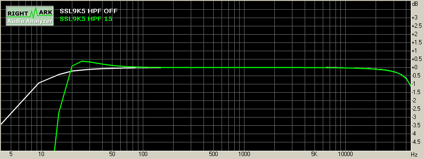
The HPF. Big saturated bass between 15Hz and 110 Hz and after, it's like a band pass filter, or a HPF with a big bell.
Maybe the trimmer is the solution?
I have record this ugly noise but i don't know how to put it here  :(

So, you understand that i need help...

thanks

ledada
 
ok ok.. i try to use the trimpot, and it's really better, no more noise but still a big bell. With a spectrum analyzer, i see for example - 72 dB at 80 Hz without the hpf and - 53 db with the hpf on ( minimum frequency). Is it normal ?

 
Ledada, on the pic is mine ssl9k5 with HPF off and HPF on ( freq pot full counterclockwise)... I did the calibration with mine, I think its ok and sounds nice

SSL9k5spectrum.png
 
SSL9KBoardCut.jpg


There is a picture here.  If you look at that pad with a magnifier, you will see that there is a connection there (right at the top of the picture, not visible in the picture.  All you have to do is cut till the pad isn't connected to the plane any more.  Mine was two tiny slices with a razor.

ledada said:
this is my first message here... and first message on a forum !
I'm a new diyer, i have build a VP26 without problem ( it's really easy, isn't it ?), and now i build a SSL9K5, and i have some problems. My first test was - in part- good, without the led meter.

My first problem :

With the led meter, R1 is destroyed... OK it's because there is a shortcut. Bruno 2000 says "there is an unwanted connection between the power eyelet and the top ground plane of the meter board."
Another try without the meter board... ok. So i have to cut the extra copper but i don't know how and where to do that. have i to cut on 1 or 2
or both ?
8130602954_947a8a2d0b_m.jpg


My second problem :

The HPF. Big saturated bass between 15Hz and 110 Hz and after, it's like a band pass filter, or a HPF with a big bell.
Maybe the trimmer is the solution?
I have record this ugly noise but i don't know how to put it here  :(

So, you understand that i need help...

thanks

ledada
 
I finally understood what to do !!

Everything work, so thanks to everybody.

Diy is completely addictive, i have to work on another project, a compressor... Any idea for a beginner ? GSSL ? 1176 ?

 
I got a pair of 9k and a pair of 4k up and running.  They both sound great.  Thank you to all who contributed.

I found out the hard way that the 4k phantom is routed such that an led is required, but the 9k does not.  I don't know if this is on purpose, but its a variation from the 4k schematic. So I tested all without the LEDs and found the 9k to work the 4k were hugely distorted.  It turned out that I had no power to the Countryman DI that I used to apply a signal.  I didn't realize that it was not the preamp until I tried a different DI the had a power LED.  But just like an 80s sitcom, all is well in the end.

I used a EA2622 for the 4k transformer.  But I reconfigured the circuit such that the primaries were in parallel, rather than series.  This gave me a 1:7 ratio rather than a 1:5 that is design.  For a zobel, I used a 5.1k and a 220pf, as used in the stock API 312 design.  I figured those would be appropriate since my tranny is a copy of the original 2622.

My only question is this: will the change in gain affect the db result on the LED meter, or does the meter circuit not depend on the gain level?  I think the meter scale will be independent of the transformer, but I wanted to verify.

- Andre
 
Andre said:
I found out the hard way that the 4k phantom is routed such that an led is required, but the 9k does not. 


That's wierd.  It is identical on the schematic to the 9k.


Andre said:
But I reconfigured the circuit such that the primaries were in parallel, rather than series.  This gave me a 1:7 ratio rather than a 1:5 that is design.
My only question is this: will the change in gain affect the db result on the LED meter, or does the meter circuit not depend on the gain level?  I think the meter scale will be independent of the transformer, but I wanted to verify.

I built some alternative meter board for the 9k5/4k5 so I looked into it quite a bit.  The way the meter circuit works, as shown on the schematic is basically a copy of the meter circuit in the LM391x data sheets.  In order to chain two of the LM391x chips the signal is split after the amp (but before the EQ) into a normal level signal and one that is several db lower.  The second is used to drive the top 4 led's.  The meter is measuring output levels of the preamp (prior to EQ) and should behave as it does in the unmodified 9k5/4k5.  (better minds could differ).

That said by increasing the input transformer ratio you have made the preamp higher gain, and therefore it will generate higher output and overload sooner for a given input signal.  And of course a signal that saturates the transformer on your arrangement might not do so on the lower ratio input.  But the accuracy of the metering for any device "downstream" of the preamp should be as accurate as it was before.

I do have a questions, although it is sort of out of my depth, but in case someone knows, here it is: does changing the transformer to Parallel windings rather than series winding change it's secondary impedance for a given mic (mic's output Z reflects onto the secondary right?). According to the calculation published on the Jensen Transformers side the optimum noise performance can be calculated ( I  did the math for 5534 and 5534A specs, and it shows 5534 optimum is 6.66K, and for 5534A  8.75K).  I don't know if your change effectively raises or lowers the 10k secondary impedance of that transformers, or leaves it unchanged, or how the zobel choice effects this.  But I would be interested if anyone knows this stuff.
 
Thanks for the info Bruce. 

The impedance matching was part of the reason to wire the transformer primaries in parallel.  If I understand correctly, the secondary impedance equals the primary times the turns ratio squared.  So the circuit's design secondary impedance is 150*5^2, or 3750 ohms.  My options were 1.8k (1:3.5 series) or 7.3k (1:7 parallel).  Seeing the optimal noise impedance for 5534a makes me think I went the better route.  If recall correctly, I'm using 5534an from On Semi.  The other reason to go with parallel primaries is because that's how this transformer is used everywhere else- I figured it was a safe bet.  As far as the Zobel goes... That's beyond my level of knowledge. Again, I just borrowed values.
 
Well that makes sense to me.

Note that the primary calculation includes the mic's output impedance I am pretty sure ( so it depends to some extent on the mic)


I wonder if the Zobel network contributes to the impedance in this calculation.  The 5.1K would lower the impedance a good bit if so.


b
 
Hey Joe did you ever try other input xfmr's for the 4k ?
was there any consensus on what people liked the most for this  ?

I wanted to go with Lundahls but can't find a good price on them and it's
too expensive to experiment with transformers
 
hey guys, does the build have to be calibrated since there are two pots sitting on the board (I'm aware that one's for the HPF which i deactivated). (9k 500 build).

curiously, one build is not giving anything out at all and the other at the utmost highest gain. I figure one of the pots has to be adjusted?

Mike
 
Back
Top