bruno2000
Well-known member
<shameless plug>
Gustav now has the 4K boards in stock, and ready to ship.
Best,
Bruno2000
</shameless plug>
Gustav now has the 4K boards in stock, and ready to ship.
Best,
Bruno2000
</shameless plug>


bruce0 said:Glad rectifier helped.
And... Well I can't speak to the fire...
But Maybe you should get a loupe and look at each and every solder joint and look for bridges or unsoldered parts.
If it was me I would check all the stupid stuff, IC's oriented correctly, diodes oriented correctly. all parts installed. All junctions soldered. No solder bridges.
With respect to the oscillation
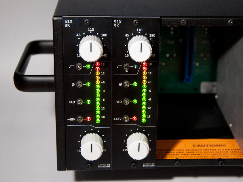
i did have very bad oscillation on one unit when I first put it together, especially with the HPF turned on, (one just worked fine, the other whooped when I turned on the HPF). I fixed mine by doing the HPF calibration procedure (to fix it all you need actually is just the first step, which is to turn one of the pots all the way one way ( left I think, maybe right?)... look at bruno's procedure. After that the oscillation was gone.).
Switches popping... I have no idea. which switches pop? That might give us a clue. Switch pops made sense with the Phase switch and DC on on output... but I have no noisy pops.
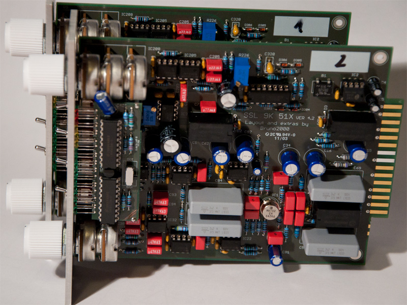
bruce0 said:10R Fused
Is a 10 ohm resistor.
In the US they are them Fusible resisters, or fireproof resistors. I don't know where they call them Fused.
In a nutshell.
What it means is you can design in a low wattage resistor, INSTEAD of designing a fuse in the circuit, and hopefully because it is fireproof it will burn out to an open circuit and protect the circuit if the current gets too high... without catching on fire or catching something else on fire . In order to determine just how fireproof or whatever they are you must read the specs... (I. E. I am sure it is possible to start a fire with a fireproof resistor under various conditions).
In these 9k boards.. The "10R Fused" resistors act as a fuse for the circuit. If yours is burning out perhaps you have some solder bridge across adjacent pads, or some other short.
b
:
bruno2000 said:How do you like the sound?
audiorock said:Hi,
what are the alternative models of Cinemag CM-75101APC for SSL4k series? (jensen, lundahl, OEP, etc)??
Enter your email address to join:


