ding
Well-known member
Where are people getting these elusive 3.2uf 450v wet tantalums that I can't seem to find anywhere? I've been looking for days on the interwebs. 
Delta Sigma said:I think someone mentioned using these guys:
http://www.ebay.com/itm/2-Sprague-109D365X0125C2-3-6uF-125V-20-Wet-Tantalum-Capacitors-/191130283180
Mouser has brand new wet tants but they're in the $70 ea range.
ding said:These are 125v. I don't think they will stand up to the task. Who ever is using these I would be very careful cause the voltage could really damage the cap.
bockaudio said:I've never seen the wet tant in a 251 short out (I have seen loss of capacitance), though I've seen plenty of tants short out in ATR124 decks taking down the whole machine (smoke optional).
I have also seen original T14/1 xfmrs go open. That wire is mighty fine.
IF your new build mic does not copy the exact footprint of the 251, you should have more room for other cap options. Then you can listen and decide for yourself. But in a vintage 251, space is at a premium so the original cap is a must, unless you are willing to crack the plexiglass body, as some repairs guys are willing to do. FYI there is no electrolytic that will fit in that space that sounds good so don't bother.
Yes you can use a 125v cap, though it's safer with higher tolerances. The occasion of reaching 125v across the cap occurs at power up, when the B+ is there but the tube hasn't fully heated. Reaching full B+ once the tube is heated will likely not happen during normal use, unless you stick it in a kick drum.
I have found NOS went tants (of the value you need for this mic), even recently, so I know they are out there
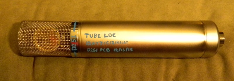
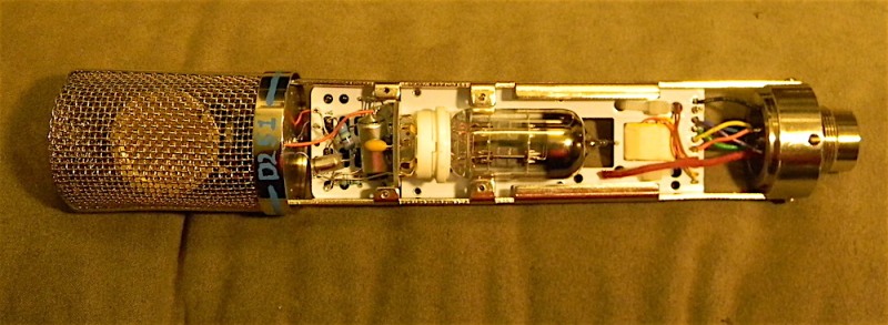
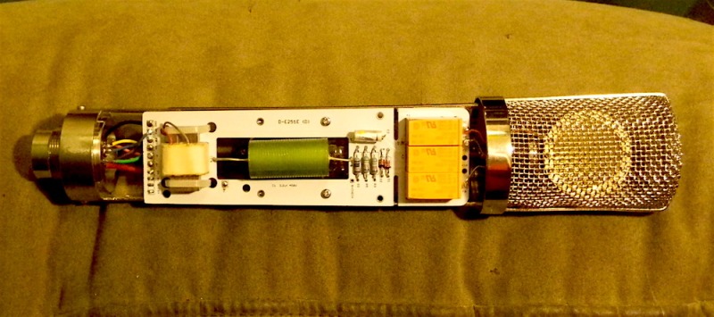
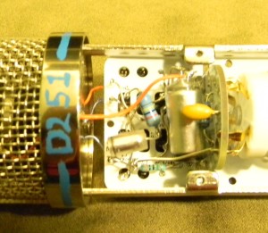
andybaker28 said:Hi again,
I am having trouble figuring out how to lower my capsule voltage to 55V. I have tried looking at the schematic but just able to know for sure what I am doing! I have read that I need to change a resistor on the voltage divider, but I am not able to understand..
Thanks for any help
Andy
midwayfair said:andybaker28 said:Hi again,
I am having trouble figuring out how to lower my capsule voltage to 55V. I have tried looking at the schematic but just able to know for sure what I am doing! I have read that I need to change a resistor on the voltage divider, but I am not able to understand..
Thanks for any help
Andy
You're looking for two high-value resistors that cut the voltage in half as a reference voltage before a VERY VERY high value resistor that provides the charging voltage for the capsule on the capsule's side of the input capacitor. Trace backward through the schematic from the capsule connection and you should find these. Hopefully that's enough of a hint. (There aren't many components in the mic itself.)
Right now the two high-value resistors take a B+ of 120V and make it 60V. If you aren't sure what value to use for the voltage divider, here's a calculator: http://www.raltron.com/cust/tools/voltage_divider.asp
andybaker28 said:midwayfair said:andybaker28 said:Hi again,
I am having trouble figuring out how to lower my capsule voltage to 55V. I have tried looking at the schematic but just able to know for sure what I am doing! I have read that I need to change a resistor on the voltage divider, but I am not able to understand..
Thanks for any help
Andy
You're looking for two high-value resistors that cut the voltage in half as a reference voltage before a VERY VERY high value resistor that provides the charging voltage for the capsule on the capsule's side of the input capacitor. Trace backward through the schematic from the capsule connection and you should find these. Hopefully that's enough of a hint. (There aren't many components in the mic itself.)
Right now the two high-value resistors take a B+ of 120V and make it 60V. If you aren't sure what value to use for the voltage divider, here's a calculator: http://www.raltron.com/cust/tools/voltage_divider.asp
Hi there and thanks so much. I tried to follow what you said. I am trying to learn! I am thinking that maybe I could try putting a 13K ohm resistor in place of R5, and a 15K R3? Would that do what I need? I do appreciate it very much!
Andy
midwayfair said:andybaker28 said:midwayfair said:andybaker28 said:Hi again,
I am having trouble figuring out how to lower my capsule voltage to 55V. I have tried looking at the schematic but just able to know for sure what I am doing! I have read that I need to change a resistor on the voltage divider, but I am not able to understand..
Thanks for any help
Andy
You're looking for two high-value resistors that cut the voltage in half as a reference voltage before a VERY VERY high value resistor that provides the charging voltage for the capsule on the capsule's side of the input capacitor. Trace backward through the schematic from the capsule connection and you should find these. Hopefully that's enough of a hint. (There aren't many components in the mic itself.)
Right now the two high-value resistors take a B+ of 120V and make it 60V. If you aren't sure what value to use for the voltage divider, here's a calculator: http://www.raltron.com/cust/tools/voltage_divider.asp
Hi there and thanks so much. I tried to follow what you said. I am trying to learn! I am thinking that maybe I could try putting a 13K ohm resistor in place of R5, and a 15K R3? Would that do what I need? I do appreciate it very much!
Andy
Those resistors are presently 500K. 15K and 13K are orders of magnitude smaller. I suppose you could go do some calculations to find out what the demands on the power supply and components would be if you used resistors that small, but I think it's fair to tell you that you should stick to values closer to what's already in the microphone.
EDIT: You can do it with two standard (easy-to-find) values, as well.
andybaker28 said:Hi and thank you again! I had another look and have attempted again at some common value resistors closer to original. I am a bit confused on how the relationship between the two resistors values work. In the calculator it mentions R1 and R2, if the values of these two are reversed it has a change on the output voltage. In the microphone schematic it appears to my pea brain that on the 251 diagram R3 would act as R1 on the calculator, and R5 would act as R2 on the calculator. I wonder if that is correct. I do appreciate your help. I am thinking now then that possibly R3 should be a 560K and R5 should be a 470K. This would make my voltage 54.7, I think…
Andy
ding said:andybaker28 said:Hi and thank you again! I had another look and have attempted again at some common value resistors closer to original. I am a bit confused on how the relationship between the two resistors values work. In the calculator it mentions R1 and R2, if the values of these two are reversed it has a change on the output voltage. In the microphone schematic it appears to my pea brain that on the 251 diagram R3 would act as R1 on the calculator, and R5 would act as R2 on the calculator. I wonder if that is correct. I do appreciate your help. I am thinking now then that possibly R3 should be a 560K and R5 should be a 470K. This would make my voltage 54.7, I think…
Andy
Hey Andy, did you get that going? How does it sound?
andybaker28 said:ding said:andybaker28 said:Hi and thank you again! I had another look and have attempted again at some common value resistors closer to original. I am a bit confused on how the relationship between the two resistors values work. In the calculator it mentions R1 and R2, if the values of these two are reversed it has a change on the output voltage. In the microphone schematic it appears to my pea brain that on the 251 diagram R3 would act as R1 on the calculator, and R5 would act as R2 on the calculator. I wonder if that is correct. I do appreciate your help. I am thinking now then that possibly R3 should be a 560K and R5 should be a 470K. This would make my voltage 54.7, I think…
Andy
Hey Andy, did you get that going? How does it sound?
Hi there, I actually did buy the resistors but not yet installed them, in the meantime though I did switch the .22 uf Tantalum to a 100uf Tantalum and did not hear a change. Then later switched the 100uf Tantalum to a 100uf gold panasonic electrolytic and man the bottom really came up then. I did not have much time to test it on acoustic guitar yet, but the low on my vocal was much more without being muddy or too much. I will try the resistor change to lower the voltage down to 55V soon, I was sort of wanting to see if what I had calculated was correct first. I guess it won't damage anything to try! I will keep you posted as I proceed!
Thanks again
Andy
Andy
JessJackson said:is it a wet tant andy