Telefunken ELA M 251 Clone Tube Microphone Build Thread (D-Ela M 251E)

GroupDIY Audio Forum

Help Support GroupDIY Audio Forum:

This site may earn a commission from merchant affiliate links, including eBay, Amazon, and others.
ln76d said:
440pF is little bit too much for C2 or your capsule is overbrighted (yes these chinese "ck12" can sound different a little bit).
Desolder these caps, or at least both from one side, and make voice test.
R4 is another posibility and also can causing lack of low end.
1M is really too small, i would think about 100M or 1G but not 1M  :)
30M and 8M are also small values - but if you want to recreate something at least in 20% similar to the original then these are ok.
Rest differences of the parts are ok.
If this wouldn't help - try to change 22uF fine gold to something else (these caps sometimes can be tricky) if this not help, try different output cap, but JB usual works better than fine ;)

Interesting. C2 (usually 100pF) is what I started with but it was indeed much too bright.  I worked my way up to 440 and found it to sit well.

Wondering why the 30M would be to low value when this is the value on the Schematic.  I will try a 250M since i have one here.  But 30M really made the mic sound odd.  Also, on the Official 251 point to point on Acrylic build and support thread it would seem that he has put in a 250M at this point.  That being said I have seen a pic online where this was 800K. 
I'll keep trying.  At the moment it sounds pretty darn good.  Just can't handle a loud vocal.

 
Ok, I've tried putting in a 250M in place of the 1M for R4.  Sounded awful.  Fuzzy, had a weird DC offset and it was 10db quieter.  I put back the 1M for now.  Sounds great.  I just can't record loud vocals with it but that seldom happens.  Here's a clip for anyone interested. Mic > BAE 1073 DMP - no comp, no eq, only used a bit of VSS reverb on the vocals:

https://www.dropbox.com/s/jekmx6mqog2mcht/I%20can%27t%20help%20-%20251%20test%201M%20ohm%202W%20resistor..mp3?dl=0
 
ln76d said:
Definately you screwed up something if it sound worse with higher resistance.

Apparently I screwed up good. The person I made this mic for is blown away.

Whatever. If th shoe fits.....
 
I would check all, especially if you did this mike for someone else.
It's not about, that you need change resistor, because it should be higher in theory.
Is worth to know, why it distorts and what causing that. Wih the time it can be worse.
I would really checked polystyrene caps - or check mike without it.
Please remember that polystyrene can microphonic also.
 
ln76d said:
I would check all, especially if you did this mike for someone else.
It's not about, that you need change resistor, because it should be higher in theory.
Is worth to know, why it distorts and what causing that. Wih the time it can be worse.
I would really checked polystyrene caps - or check mike without it.
Please remember that polystyrene can microphonic also.

Cheers, that's a good point. I will check it when my capsule gets returned from Peluso.
 
Here's modified schematic for use single backplate capsule (as from groupbuy for example) to get cardioid and omni patterns in Dan's circuit. It's something like ELA M250E. Utilize less parts and SPDT switch instead SP3T.
Hope that Michael don't mind that i used his drawings ;)
Dan, if you could check is it everything proper according to the PCB connections, it would be great!
 

Attachments

  • ELA M250 mod.png
    ELA M250 mod.png
    328.4 KB
Hey Guys,

i have the following setup:

Tim Campbell Capsule
Standard Mouser + PCB
Beesneez Body
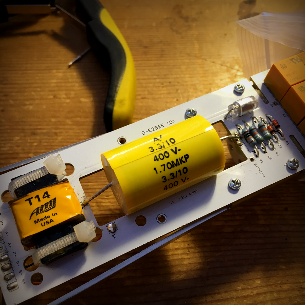
AMI T14
Neve 1073 Preamp

I have tried many C1 and stuck with
the one in the picture. I also changed C3 to 100 uf
and it gave the Low End a boost around 2-3 DB.

The EQ curve is really really good/close in comparison with
an original ELA M 251 but the Low End (150-200Hz)
needs another boost around 3-4 DB.

- "Reduce 0.5R to Ground" - Do you mean R5 or R3 ?
    -> How do i do this ?

-"Grid Resistor higher" - Do you mean R4 ?

Any other tryouts ?


THANKS GUYS

 
Just completed this microphone. What a fun build. Congratz Dany, this one rock some ***! It sounds freakingly awesome, no noise, no hum, no what so ever else than awesomeness  8) ok seriously, I like it.

15317796_1163219830429636_2410926642325743705_n.jpg


15385385_1163221287096157_4343295828579453198_o.jpg


15443208_1163221510429468_8529965010689125681_o.jpg
 
Will need to reverse 2 lead. I didn't pay attention to the gage and used 26ga for the heater. Don't think it's really dramatic, but we never know
 
Sorry for the noob question guys...just trying to finish this build.  Can someone tell me the xlr 7 pin points for the circuit?  It was pretty much paint by numbers for the C12 build but this one not so much :)  Thanks!


Mic PCB=XLR 7 pins
GND = 7?
OMN= ?
F8=?
H+=?
A-=?
A+=?

 
It's up to you to decide all these assignement. Just remember them and and stick to them on all 7 pin xlr you'll have to make on this build
 
Great...Thanks! 

BTW...when calibrating PSU and I am getting 139V and it climbs down to around 120 or then it fluctuates a bit.  Should I be getting a constant value on the  B+ and Bias?  Should I get 120V immediately upon powering?  I am getting a constant on H+ of 6.3V. 
 
NuSoundz said:
BTW...when calibrating PSU and I am getting 139V and it climbs down to around 120 or then it fluctuates a bit.  Should I be getting a constant value on the  B+ and Bias?  Should I get 120V immediately upon powering?  I am getting a constant on H+ of 6.3V. 

It's unregulated supply for B+ so it will be fluctuating. H+ is regulated so it's constant.
 
So to be clear, its Okay to be at such a high voltage 136V-139V when first making contact and then letting it settle in around 120V?  I just don't want to cause any damage to any components :-\  Please feel free to describe in as much detail what I should be seeing examples etc.  Thanks!!
 
If your capacitors are rated for 120V or lower, some may blown. Otherwise nothing should happend, maybe just capsule will suck diaphragm to backplate. That's the deal with unregulated supplies. BTW. you should have potentiometer inside PSU to reduce voltage.
 
Got build complete, just getting a hum on Cardioid and Omni, not Fig 8...any ideas?  Any chance it's the capsule?
 
Back
Top