Transistor amp from scratch

GroupDIY Audio Forum

Help Support GroupDIY Audio Forum:

This site may earn a commission from merchant affiliate links, including eBay, Amazon, and others.

DaveP

Well-known member
Joined
Nov 8, 2005
Messages
3,028
Location
France
Since I joined Groupdiy about 17 years ago, I have been making gear for other people, just for a change I decided to make a transistor amp for myself.

I don't like PCB's so this will be made as far as possible like I would make a tube amp. The circuit is by Mullard from around 1970.

First the box.


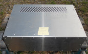
I have attached a generous heatsink to some bakelite board and it fits inside the box OK


I covered it with masking tape to measure carefully for the component holes.


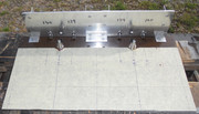
The components will be soldered on the other side with wire.

I originally planned to make a hifi tube amp but this seemed quicker and a good way to explore a new technique.

Best
DaveP
 
Cool; which Mullard amp is it? I built the one with the BD139 output transistors not long after the design came out. It was surprisingly clean.

Edit: I also had a Sinclair Z12 in the late 60s - I remember using it one year in the school play.
I still have a pair of Sinclair Z30 amps in a wooden box I made probably 50 years ago.

Cheers

Ian
 
That is definitely the one. Looking at it now I would think there is probably a better choice for TR2 . The BD139 they use has a huge rage of hfe from 25 to 250. Maybe use a selected one?

Cheers

Ian
 
The BD139 came in a pack of 5 and they were all around 134/5 hfe.

Why I dislike PCB's?
Fragility, foil lifting, copper corrosion. With point to point you can cut a component out and replace it without making too much mess.

best
DaveP
 
Why I dislike PCB's?
Fragility, foil lifting, copper corrosion. With point to point you can cut a component out and replace it without making too much mess.

Have to say it seems you've been very unlucky with your pcb experiences.
  • Fragility - no they aren't. At least if you use standard 1.6mm FR4.
  • foil lifting - need better quality fabrication
  • copper corrosion - if this is a problem then you need environmental protection in the form of some sort of conformal coating or 'varnish'.
  • With point to point you can cut a component out and replace it without making too much mess. - same with pcb really. And with SMT.
 
Last edited:
I don't need to fabricate a pcb for a one-off like this amp.

Indeed. Apart from one smallish pcb where I had twenty off made cheaply, all my DIY stuff is on stripboard and wires.
But the day job has often involved putting pcb assemblies into harsh environments - automotive / extremes of temperature and humidity (eg arctic to tropical) etc.
PCB quality shows up when reworking - do the pads etc lift - and with multilayer pcbs delamination may occur if it's not properly put together.
 
Dave and Mr. Carlson on youtube are the rare exceptions of people who do amazingly clean PtP builds, because whenever people bring me things to fix, they're a mess, and getting access to what I need to replace is often a nightmare, and then I find myself "fixing" what the builder did while I'm at it.

Anyway, now back to our regularly scheduled programming.
 
Indeed. Apart from one smallish pcb where I had twenty off made cheaply, all my DIY stuff is on stripboard and wires.
But the day job has often involved putting pcb assemblies into harsh environments - automotive / extremes of temperature and humidity (eg arctic to tropical) etc.
PCB quality shows up when reworking - do the pads etc lift - and with multilayer pcbs delamination may occur if it's not properly put together.
[all my DIY stuff is on stripboard and wires] -- And.....all of -- my DIY stuff -- is always designed on PCB's and is designed in such a manner to eliminate all of the wires!!! Perhaps doing things in this fashion is normal for me to do since my "day job" is being a "Senior Electronics Mechanical Packaging & PCB Designer" and everything that I design for others is designed in the exact same manner. I guess.....

/
 
I think its the same one, BD139/BD140 complimentary


It is supposed to be 0.1% distortion.

best
DaveP
What is the recommended amount of DC current availability for this circuit.....times two???

Will a 36VDC @ 1-Amp power-supply be adequate enough? It appears as though the BD139/140 output transistors are rated at 12.5-Watts, so 2-channels would come to 25-Watts maximum and then "25-Watts divided by 36-Volts" comes to basically 700mA.....so.....1-Amp to allow for some headroom.

/
 
Last edited:
[all my DIY stuff is on stripboard and wires] -- And.....all of -- my DIY stuff -- is always designed on PCB's and is designed in such a manner to eliminate all of the wires!!! Perhaps doing things in this fashion is normal for me to do since my "day job" is being a "Senior Electronics Mechanical Packaging & PCB Designer" and everything that I design for others is designed in the exact same manner. I guess.....

/

Sounds good. My "stripboard & wire" things are one off efforts / prototypes. If I were making more then I'd look to go PCB.
 
The distortion quoted is an expected 'average' of a bunch of units using random unselected transistors so a combination of Hfe and collector base capacitance and cutoff frequency of all except the bias setting transistor. Selecting or specifying 'better' transistors is one way to make a marginal improvement to a circuit that is inherently flawed BUT for the time was reasonable and dependable in it's inadequacies. Using transistors with high cutoff frequency can lead to different problems and be more layout critical. Distortion also needs to be specified more accurately as crossover 'spikes' can be worse than second or third (other) harmonics. JLLH (RIP) discussed the best place to use the output transistors with highest Hfe on his simple class A power amp design which would never be 'fantastic' because of the limitations of a single input transistor but like peeling onions there are always more layers to work through with the ultimate irony that eventually they are branded as 'sterile' because there is hardly any distortion (compared to the signal sources and speakers). Build it, enjoy some good music, move on!
 
The 'bootstrap capacitor is too low a value for use at LF so far better to use the output transistors in 'darlington' or a compound variation to reduce the 'base' current requirement for the output. This was discussed in a technical paper by Texas Instruments in the 1970's in and among proposing getting a low voltage power supply feed from an overwind on your turntable (record deck) motor! Schematic (the circuit) design is one set of issues but then implementation is another so a good design is easy to mess up by careless layout and implementation.
 
Back
Top