Transistor amp from scratch

GroupDIY Audio Forum

Help Support GroupDIY Audio Forum:

This site may earn a commission from merchant affiliate links, including eBay, Amazon, and others.
To finish off this topic:-
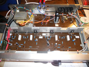
I gutted a Marantz 30W/channel amp that had failed and built this circuit inside it:-


This is what the finished board looked like


The advantage of this circuit is that it uses darlington transistors so the driver transistor has a much easier life.

I don't know why the original circuit was prone to oscillation but this one does not suffer from that problem. The new Stones album Hackney Diamonds sounds fantastic on this with my big monitor speakers
https://groupdiy.com/threads/3-way-monitors-from-scratch.68941/

best
DaveP
 
It should sound good. It's a low nfb circuit! New modern caps.
I have a Luxman with a similar ckt. Sounds very good with my TV.

If you regulated the power supply it would sound even better, IMHO. The 2nd stage uses the -35 volt rail as its AC ground rail. The stiffer that is the less the output load can modulate it. With just one supply for both channels there is some inter channel crosstalk through that rail. Subtle but still there. Can affect the LF response. Tighter bass can be had with regulation.

Caveat* I did not read through this whole thread* too long.
Enjoy
 
Last edited:
Can easily have 60dB or more open loop gain especially as the second stage is bootstrapped. Closed loop gain is 26dB so there is 34dB nfb. Not what I would call low.

Cheers

Ian
We're both speculating here but from what I see the bootstrap equalizes the drive between the upper and lower opt transistors. You could be right but my guess is lower.

I just looked up the db attenuation for the NFB voltage divider and it is 15.7195 db open loop would be 26 + 15.7 = 41 db open loop. Did I get that right? 15.71db is fairly low NFB IMHO. That seems reasonable for that vintage circuit. They weren't looking for .00000001% THD in those days.
26dB is the closed loop gain determined by the 47K and 2K2 resistors (~27dB). Not sure what you mean by the nfb attanuator.

Either way, the answer will be determined by what the actual open loop gain is. I might do a quick sim over the weekend to get a realistic figure,

I agree they were not aiming ofr extremely low THD in those days but they were aiming for 0.1% (which is what the tube amps that preceded them did) and I suspect you need a lot more than 15dB of nfb to achieve that.

Cheers

ian
 
Ian,

You're assessment is probably spot on. Let me know if you model it in spice.

The NFB attenuator is R8 2.2k and R16 47k which form a 33 db attenuator, ignoring the bass rolloff cap C3 at mid band. ( I made a mistake and put in 22k for R8 giving 15 db attenuation. So I was wrong about the NFB, it's 33 db and when added to the overall gain makes it about 59 db open loop gain. It's working backwards knowing the overall gain and NFB net attenuation.

Since the circuit is basically an op amp the - input (base T2) has to be what the + input (T1 base) is. So if the overall gain is 26 or so db and the NFB attenuator reduces the output by 33 db to T2 base the open loop should be about 56 db.

I used this calculator rather than drag myself through logs. https://www.digikey.com/en/resources/conversion-calculators/conversion-calculator-attenuator

I used a pi attenuator calculator but ignored the input resistor since it is being driven by the output stage, it's negligible.

Amp forensics, your honor.
 
Yes, not typical.

That trim also adjusts the static current/nominal DC operating point of the string driving the output devices. The further away from 0V nominal, the more error the input LTP has to correct for.

JR
Which begs the question - what are the component tolerance issues which mean we need a trimmer anyway?

T4 has a collector current of about 5mA (from ~30V across R12/R13) and its typical gain is 100, so the base current is then 50uA. The drop across R5 is then 0.25V or so, meaning R3 has ~ 0.9V across it, leading to T1 having a collector current of ~ 2mA.

But... this is quite dependent on T4 gain, if it were 50 the numbers would be 100uA, 0.5V, 1.15V and about 2.5mA for T1. So, if we want T1 and T2 to have equal collector currents that's a range of 4 to 5mA through T3 and RV1.

Unless I'm mistaken, though, we won't get more than 3mA through T3 even with RV1 off, so we'll never actually reach balance. Can that be right?
 
The circuit comes from page 95 of electronic circuits handbook by Michael Tooley. 1988.
Response is 15Hz to 50kHz, Distortion at 30W into 8 ohms is 0.05%. Noise -90dB at 30W.
Voltage gain is 20 so 1V is required for full output, an ideal output from a CD player.

Voyager is correct, the LTP is 2.76mA and T4 is 5.5mA

Hope that helps
DaveP
 

Latest posts

Back
Top