Transistor amp from scratch

GroupDIY Audio Forum

Help Support GroupDIY Audio Forum:

This site may earn a commission from merchant affiliate links, including eBay, Amazon, and others.
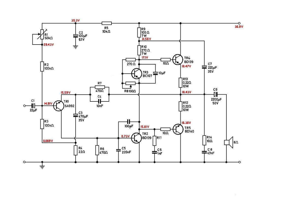
2. Add Collector to Base cap so TR3 never can oscillate. Maybe 100pf?

This is a common addition but Mullard didn't add it to this design.

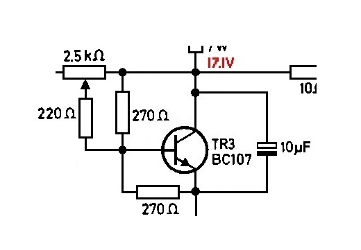
3. Add cap across TR3, Collector to Emitter. Maybe 10uF?

I have never seen this done, what does it do?

4. May need Base stoppers to TR5 & TR6. Maybe 10-22 Ohms?

They added base stoppers to the bigger amps in the book but not to this one.

Thank you for taking the time to make suggestions, I think it wise for me to get the basic amp working before I start making "improvements"!

best
DaveP
 
The first step is to get it working without making new smoke.

[edit- you have received multiple suggestions to improve TR3. Fixed resistors from emitter to base and collector to base could give you a stable nominal operating point with trimpot open circuit. Another resistor from the trimpot wiper to base could adjust the class A current up/down some safe amount. I wouldn't overthink this.

A large electrolytic cap from base to collector could give this a slow turn on, and stiffen up the impedance driving the output stage. Likewise a cap across the entire Vbe multiplier will similarly stiffen up the drive impedance. /edit]

It is often helpful to bring up new builds with a variac so you can identify problems before they get too hot.

JR
 
Last edited:
I think that when I refitted the fins to the heatsink, the shock of the pop rivets destroyed the output transistors, the driver transistor is intact.

best
DaveP
 
Last edited:
Both TR2's (drivers) are OK, but all the TR3's and output transistors are shot.

I shall rebuild it with all the suggestions incorporated.

best
DaveP
 
Before I start, would those who made suggestions check out this revised schematic to see if I have understood correctly?

I realise that the voltages shown will be different after the changes.
best
DaveP
 
Would it be better to connect the variable pot Collecter to base then?
DaveP
not exactly... visualize what happens if the pot fails open circuit.... the class A bias goes to maximum and devices release smoke.

JR said:
Fixed resistors from emitter to base and collector to base could give you a stable nominal operating point with trimpot open circuit. Another resistor from the trimpot wiper to base could adjust the class A current up/down some safe amount. I wouldn't overthink this.

Don't over think but consider possible trimpot faults, bad solder connections, or mis-adjustments. I guarantee that in production some fraction of production would see the trimpots adjusted incorrectly. You might even do that on the bench tweaking around.
===
If the trim pot can possibly fail open circuit (or bad solder joint) it should be in the base-emitter leg where an open circuit would result in minimum class A bias current. :cool:

If you dismiss my earlier suggestion, add a resistor in series with the trimpot in your latest circuit so that the bias trimpot cannot be adjusted for maximum bias (0 ohms). (y)

JR
 
The problem is calculating the value of a series resistor for the trimpot when there is only 100 ohms to play with. I am very nervous about turning the thing on again and playing with the bias. I would like to calculate some fixed resistors to use but I am not sure of the formula.
Thank you for your your help!
best
DaveP
 
TR3 will settle at about 0.65V between base and emitter. The collector-emitter voltage Vce will be whatever gives you 0.65V across R8. The 270R resistor and R8 are a voltage divider so...

0.65 = Vce. (R8 / (270+R8))

which gives

Vce = 0.65 * (270+R8) / R8

So, as R8 gets to 0 this will go to 'infinity'.


For example, if you put 150R in series with the trimmer it will give R8 in the range 250R .. 150R, with corresponding voltage range 1.35V (TR4/TR5 just about on) to 1.8V (ought to be plenty).
 
OK sit down and crack a beer....

I can get you in the ball park. Vbe multipliers are pretty straightforward. (big) Caveat "base-emitter junction voltage is not a precise voltage but it changes with current and temperature." In the ball park should be better than out in the field somewhere.

The 270 ohm resistor feeding into the base from the collector regulates that voltage drop from base to collector to be IxR with I being the current flowing in the base to emitter resistance (the base current is considered to be negligible). I will work backwards to come up with a hypothetical resistance value for base to emitter.

To come up with a pro forma output stage voltage lets look at the voltages on the schematic you shared. The voltage drops across the two 0.22 ohm emitter degeneration resistors suggest 180 mA of class A current in one and 225 mA or so in the other... for now let's forget about the missing 40 mA?

For the sake of the very crude calculation lets ASSume that all the transistor Vbe junctions are 0.6 Vdc. Further for simplicity lets ASSume zero current flowing in the 10 ohm base resistors. The voltage according to the schematic between bases of the output power transistors are 17.1V-15.81V=1.29Vdc This is close enough to 2x0.6V plus a smidge here and there for class A bias drop across emitter resistors.

getting back to the Vbe multiplier to realize that target 1.29V across the two output stage bases the current in the 270 ohm collector -base resistor will be (17.1-(15.81+0.60))/270 so roughly 2.55 mA. For equilibrium we want that current times the trimpot resistance to equal 0.6Vdc I come up with 240 ohms for the trimpot resistance .

Caveat again... these are based on nominal base emitter voltages that in real life will vary with current and temperature.

To be safe i would prefer to begin with too little class A current rather than too much, so we want the 100 ohm trimpot wired as a rheostat (like your schematic) to have around 140 ohms in series.

Reality often reveals how crude (wrong) these estimates can be which brings me back to one of my earlier suggestions used fixed resistor for the divider feeding the base of the Vbe multiplier set for nominal output stage bias, then have the trimpot spanning across Vbe multiplier base-collector feeding another resistor from wiper into the multiplier base to trim the class A current either higher or lower as needed. If this trimpot fails open the amp returns to a stable nominal bias.

I repeat if you have a variac, you can bring the amp up to full voltage slowly to confirm it is happy.

JR
 
Voyager and JR thanks for the explanation, I will make the calculation and change the schematic.

In the meantime, this is the power supply.

best
DaveP
 
You could have saved a bridge rectifier.

Connect O and R together (=0V, "ground"), connect BK and Y to the AC input of the bridge rectifier.
+ of the bridge rectifier = +38 V, - of the bridge rectifier = -38 V.

By the way: I don't think it is wise to connect a LED over the 240 V. wires... (And before the fuse!)
 
Last edited:
Ruud,

It is not a +&- supply, it is supposed to be two independent 38V supplies for left and right channels.

The LED is marketed for 240V use.
best
DaveP
 
I have made the circuit John suggested and tested the Vce :-

It gives a variation of Vce of 1.36V to 1.03V and if the pot goes open circuit it leaves the Vce at 1.4V.
I am not sure if this will do the job or not.
best
DaveP
 
Looks good to me....

[edit- the final test is to confirm you can get at least 25mA of class A current when the devices are cold.... 5.5mV drop across the 0.22 ohm emitter resistors, while your published schematic suggests more class A bias current. /edit]

JR
 
Last edited:
I have made the circuit John suggested and tested the Vce :-

It gives a variation of Vce of 1.36V to 1.03V and if the pot goes open circuit it leaves the Vce at 1.4V.
I am not sure if this will do the job or not.
best
DaveP
Considering the most common trimmer failure is going open, I would put the trimmer in the b-e path.
Ther is no risk of bias thermal run with a high resistance in teh b-e junction.
You may want to simulate the circuit in Spice. You can STEP the value of the trimmer from zero to infinity in oder to simulate normality and fault.
 
It is not a +&- supply, it is supposed to be two independent 38V supplies for left and right channels.
Sorry, my mistake. A lot of modern amplifiers use a symmetrical supply voltage.
I doubt if there is much advantage if you get the voltages for both amplifiers from the same transformer winding.
 
I doubt if there is much advantage if you get the voltages for both amplifiers from the same transformer winding.
I expect you are right, but it was a handy transformer and I was thinking more about the capacitors being independent
best
DaveP
 
Sorry, my mistake. A lot of modern amplifiers use a symmetrical supply voltage.
I doubt if there is much advantage if you get the voltages for both amplifiers from the same transformer winding.

I expect you are right, but it was a handy transformer and I was thinking more about the capacitors being independent
best
DaveP
Separate PS were considered an audiophile feature back decades ago. In theory amplifiers with poor power supply rejection ratio might suffer degraded crosstalk. Agreed... not a concern here IMO.

In theory connecting the two capacitor banks together could support slightly higher peak output when only one channel is driven, but the major power draw during stereo playback is from bass, typically mono, so already using both PS.

JR
 
Back
Top