U47-style bodies - who can make one?

GroupDIY Audio Forum

Help Support GroupDIY Audio Forum:

This site may earn a commission from merchant affiliate links, including eBay, Amazon, and others.
Skylar , great sketchup work  :) If it's OK with you I would like to have that .skp file and compare dimensions with my U47. Also, I can try to arrange some metal work here in Serbia.
 
Martin B. Kantola said:
But is it really worth that much? It will not make the microphone magical, put the same money in a good capsule instead since you're not building a museum quality replica... Getting the exact dimensions of the U47 is no problem, I've measured them once already. Also have a bunch of original head grilles from my M7 test if it's helpful in any way.

I have to agree with you there Martin. Spending that much on a body for a DIY mic seems a bit mad, unless you are going to source top-class parts for every element of the mic, including a Neumann-quality M7, VF14, and BV8. And even at the end, we don't know for sure if the final product would be on par with a good U47.

 
Hey after all, this is diy right ?

I can't wait till someone comes up with a nice body. (no seriously I keep hitting refresh on my browser)
Skylars design looks really impressive !

I found an image on the following url which shows the capsule height pretty clearly

http://www.814pine.com/u47a.jpg

(I have nothing to do with this url-just found it in google)
hope it helps
 
Tommypiper,

I know it's not EXACTLY like a u47, as I don't have one handy from which to take measurements.
My thought process is much like bradb's in that I was just trying to build something looks similar, but
with (hopefully) closer-than-similar acoustic properties.


Martin Kantola,

I agree with you & rodabod; $400 for a mic body is slightly mad.
If you can take pictures and measurements of the head grilles and/or other parts, I can put together a more accurate design.


Moby,

My designs were done with SolidWorks. So, I've no .skp file to send you.
I can send you other formats and pdf drawings of the final design if some of the folks here can provide
measurements for a more accurate mic body design.


Arno,

Good image, thanks.


~Skylar
 
Oh yeah, bradb...

I am not opposed to a Chinese manufacturer.

The US prices I was getting were around $175-300 for a 2-piece design that was different from the one I posted in this thread.
The u47 design has more parts and would cost more.
The Chinese prices I received were $29-60 for the same 2-piece design I mentioned above.
At the time, I thought the US pricing was just too much for people to pay
(plus I didn't have the capital to make a group purchase at that price!).


The internals of the mic body could be done in any way.
I think we should do with the internal mounting whatever is most accommodating to the various DIY projects here.
So, I agree with you and think that 2 posts will probably work better.
If anyone has a good idea on what would be the most ideal internal mounting scheme, please tell me, and I'll draw it up!


~Skylar
 
Guys,
I think we're getting somewhere now! :-*

Martin, can you give some measurements? 

Skylar, check the MK7 mic thread, Max posted some screening measurements from a U147, could be a good starting point.

I think most tube mic designs here have pattern switching on the PSU, so therefore no switches need to be put on the body.

The chinese prices sound really good to me.

 
Skylar said:
If anyone has a good idea on what would be the most ideal internal mounting scheme, please tell me, and I'll draw it up!

ioaudio's mk7 pcb ?  ;D

Seriously though, 2 mounting posts will be easier for pcb mounting and surely not a problem for p2p

I think most pcbs can be mounted with small L profiles screwed on the two mounting posts.

L profiles can be any size depending on the pcb

mounting.png
 
martin can you share the U47 measurements if you still have them? bradb if you can find the time to measure that would be great also.i would do it myself if i had access to a U47. we have wire mesh measurements already from ioaudio.
i know some members want to have bodies made up for them but i'd like to  make my own.
 
I think with the diameter of the U47 clone body we're designing, most pcbs should fit with a 2 support rail internal structure.  Whatever pcb someone has can be made to work with some additional supports.


I'll try to make some measurements soon guys, very sorry i've been so crazed lately.
 
My designs were done with SolidWorks. So, I've no .skp file to send you.
Can you export as 3d dwg or dxf? Then I can import file and possibly do some editing compared to the original 47.
Edit... I checked now and I have SolidWorks  ;D I can go with original file  ;)
 
http://www.gearslutz.com/board/gearslutz-secondhand-gear-classifieds/349135-neumann-telefunken-u47-48-grill-assembly-sale.html

Matti
 
Don't know if this helps but I own a precision measuring lab (CMM's, Video and touch probe, etc.) and can do precise measuring and produce a 3D CAD file (or just fill in dimensions on a 2D print). No charge if someone has the parts that they want measured. Glad to help (if this is needed).

Jerry

I am in Cincinnati, Ohio

Advanced Measurement Labs., Inc.
 
Here's what I've put together based on the measurements Martin placed in the groupdiy gmail account.

THANK YOU MARTIN! (here's where I would put a beer icon if we still had them)

I converted from millimeters to the closest US equivalents.
I did this mainly to conform to standard US brass tube sizes.
This will also potentially make the fabrication cheaper if done in the US.
After conversion, the dimensions are off by no more than +/- 0.5mm, and in most cases far less.
On average I'd say the deviation from Martin's drawings is something like +/- 0.15mm,
which is within standard machining tolerances anyway.

I may do another version in metric, as in Martin's drawings, if necessary.

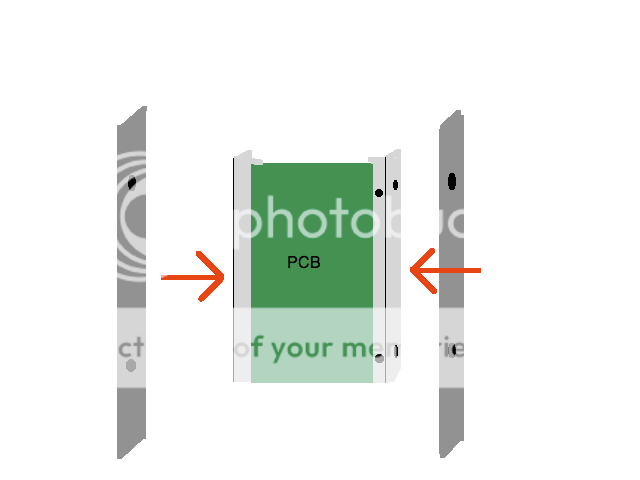
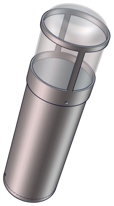
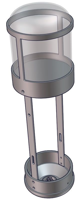
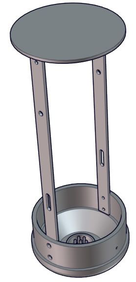
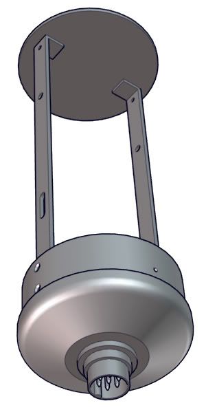
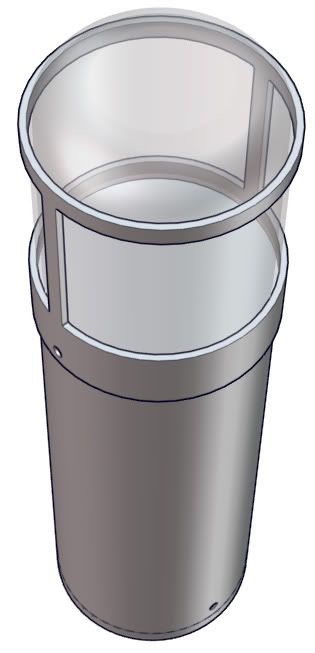
This design has two rails for mounting internals.
The position/spacing/size of the holes can be altered to better fit a variety of projects if need be.

I've added a circular capsule mounting disc to the top of the rails.
I was thinking of placing some generic holes in this disc to accommodate things like wiring & hardware.
Who has ideas for where, how many, and what size(s) for such holes? I'll most likely put one dead center at least.
Also, I'm going to add holes to the disc and the rails where they meet, so that they can be bolted together--just didn't get around to that one yet.

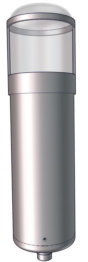
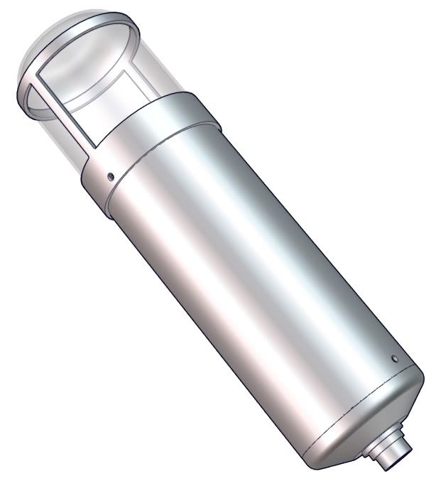
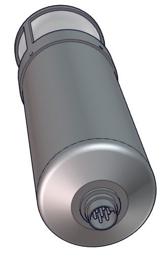
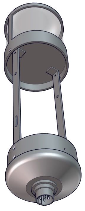
The connector shown in these images is an amphenol-tuchel T 3477 000 ($4.xx at mouser).
This is the best connector option for DIY tube mics that I have found.
If someone has a better connector option, please share.

I forgot to add one fillet on the endcap where the connector goes through...it just goes flat all of sudden and needs to be smoothed out.
I'll add this fillet on the next revision, and that part will look a lot cleaner.

With your feedback, I can refine this design further, and then we can start looking into production.
So, please give feedback ASAP, so that we can hopefully get this thing rolling!

VIDEO HERE
http://vimeo.com/2548989


u47_003_01.jpg


u47_003_02.jpg


u47_003_03.jpg


u47_003_04.jpg


u47_003_05.jpg


u47_003_06.jpg


u47_003_07.jpg


u47_003_08.jpg


u47_003_09.jpg


nice work!
My only thing would be to maybe make the flat rods (what do you call those anyway?) inside the main body into a sort of L shape to be able to bolt the PCB right on to the rods without need of extra pieces like in Arno's example..
 
Oh wow... that's impressive work Skylar!!!

BTW, the nice hand drawings were not by me but by a nice gentleman from the UK, I only measured as well as could for him. Please let me know if you need any more measurements from me.

Question regarding the output connector hole, do we have any options regarding that? Would be great if the size would match the Neumann to get the right proportions now that we have such a good looking thing... Or then use standard Neutrik for convenience. Just found a company specialized in military connectors, they seemed to have all sorts.

Martin
 

Latest posts

Back
Top