Anybody knows what these are supposed to do?

GroupDIY Audio Forum

Help Support GroupDIY Audio Forum:

This site may earn a commission from merchant affiliate links, including eBay, Amazon, and others.
According to the description, they are mainly used in tube testers to extend the life of the tester's built-in sockets; the 'savers' take all the wear and can be replaced when needed, without having to tear the tester apart.

Might be of use to those habitual 'tube rollers' out there (you know who you are . . .).
 
A "connector saver" is very common for expensive test gear, especially RF. Much cheaper to use a "saver" and have that wear out and replace as needed, instead of having to replace the connector on the actual equipment. A few hundred dollars vs many thousands so well worth it.

Not sure that similar economics would apply for tube sockets. But I could be wrong about it.

Edit : just to add there are certain connectors that can be damaged with just 1 improper mating cycle, so you really don't want your expensive test set damaged just because someone tried to stick in the wrong cable.
 
Last edited:
The idea of these things is not to reduce tube wear but rather, as others have mentioned, to protect the mounting socket in the device from excessive wear and tear when changing tubes frequently. With high-frequency tubes, you have to remember that such intermediate adapters change the capacitance properties so that, for example, an oscillator circuit no longer oscillates. There are fewer problems for audio frequency tubes. By the way, the products that are really useful are those that also have numbered pins for measurements with external measuring devices, for example:

http://www.sterkrader-radio-museum.de/Roehren REp.Adapter.htm
 
When I did my apprenticeship we had similar ones with test points for all the pins to test tubes in circuit without having to remove a chassis. They had holes that meter probes could plug into just like in the pic you posted and came with pins that could be plugged in to attach alligator clips - smaller black Bakelite ones.
 
They are larger pins aren’t they? There are adapter boards available for various tube base formats - maybe you can cobble something together using one of those although they tend to have a socket connection going to a solder point take-off but if you got an octal board with socket and ran pins off it on wires and set the board on stand-offs or to pins hard mounted to a second board designed for magnoval socket, wired to the octal board, pins pointing down into the existing magnoval socket and bolt the two boards together with stand-off spacers. You could either uses the provided solder points on each rectangular board for the interconnect or cut them down for a neater job and solder the wire to where the socket connects on one and the pins connect on the other. The wires would need to be a bit longer to allow iron access and then cram them when bolting the boards together. Just a thought.
If you could find a tube saver for magnoval you could rip it apart and top it with an octal socket.
 
I ran into a similar problem with a test fixture for octal tubes: after 100 or so insertions, the internal pins started to pull from the socket and would no longer hold firmly.

Rather than wiring up a bunch of different octal tube bases, I instead bought 100 of these:

0002081002.JPG

These are the pins that go inside 12V Molex connectors used in PC power supplies, and are less than 5c each. The internal dimension is almost exactly the same as an octal tube pin, so I just plug in the 6 wires needed directly to the tube being tested (two heaters, a cathode, the grid, the plate, and suppressor).

It's easy to re-tighten with a pair of needle-nose pliers, and can easily be replaced.
 
Yes, that's more or less what I was thinking. I don't know if magnoval plugs exist, since the idea was to do without a base, just like noval...
The pin size of the B9D is 1.27mm which is the same size as a lot of header pin strips. I’ve used these before for many things - cutting pins off with the plastic section intact - there’s an indentation between each pin which makes it easy to cut with a box cutter. I’ve used header pin strips and sockets cut to size to refit Juno 106 voice filter chips (a custom Roland pcb with smd IC’s and other components) as the motherboard pcb has ultra-thin tracks prone to damage. These pins could be wired to an octal base mounted on a blank board and this board mounted to the board with the magnoval sockets using standoffs. Height may be a problem?
Octal pins are 2.4mm dia so the connector pins shown above would be too large for the magnoval base. Molex pins are 1.57, 2.13 and 2.36mm (which fit the octal socket)
 
Yes, I figured that out.

I've looked for them, didn't find any...

Do you have reference or link? All the ones I can see are 0.6mm 2.54mm pitch.
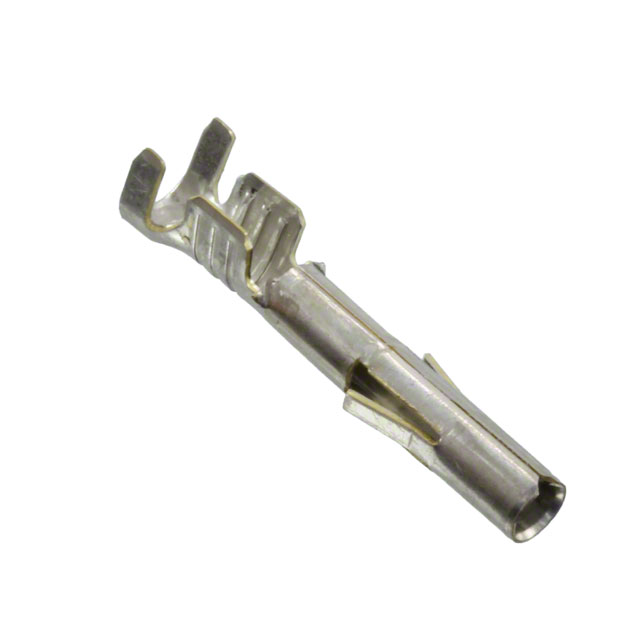
It’s been quite a while since I got those - they were some sort of automotive type but you can get individual pins either 0.049” or 0.05” pins - Digikey or others
0.049” 1.24mm Mill-Max PC Pin connectors 3139 series
https://www.digikey.com.au/en/produ...AHsoBtEWADgBZYQBdEgBwBcoQBldgJwCWAOwDmIAL6SgA

0.05” 1.27mm Mill-Max 4123 series or other brands
https://www.digikey.com.au/en/produ...HsoBtEAdkQCYBmEAXRIAcAXKEAZQ4CcAlgDsA5iAC+UoA
 
Back
Top