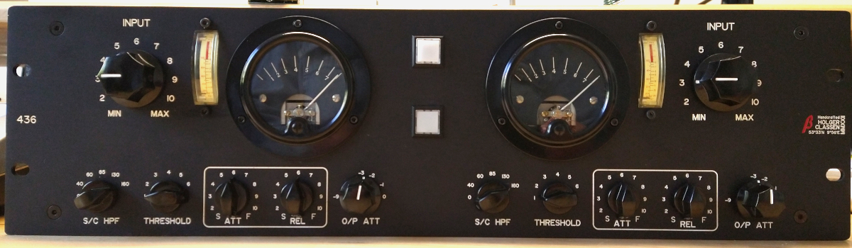
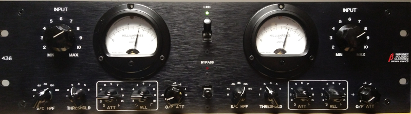
I have also finished my build. I ve used LL1540s the Sowter 1232 for my build. I could grab a pair of small 1mA Honeywell MM1 Meters on Ebay for about 65 Euro. I also tried to buy directly from Jewell Company NOS MM2 Meters. But their behavoir was so rude - neeeevvvveerr again. So a snooty, disgusting company. Bäaah...

The Compressor is in my opinion super clean, really fast, it has a very expensive sounding texture. Its difficult to get this piece really dirty sounding, hard to get it pumpin'. Like SSL on Tubes.... Wow....
Nothing to mention, no real problems with the build. It works excellent.
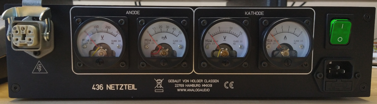
My Power TX is a customer made TX, with 0.2A 215V secondary, 4A 8V secondary and 1A 12V secondary from Audiophonics France. I have 315V DC after the B+ Bridge and about 15V Voltage Drop over R1. As for B+ Rtrim I ve used 1K -> total 48K for R3+Rtrim to get about 260V. That works super and the Components like the heatsink and resistors only gets slighly warm within the B+ PSU circuit. The heater PSU Circuit also works perfectly. My secondary shows 8.3V AC. The Input Voltage before of the TL338 regulator shows no necissitiy to tweak the Voltage down. The heatsink gets not really hot.
As for the meters I also think you will really need a 1mA DC Meter or they will not get adjusted within the range. The Meter adjustments also affect the other calibration adjustments. So it required more calibration cycles. I used a 1kHz Signal with +5dBu on the input and adjusted a 5dB Compression / Voltage Drop to 0dBu on the Output with the compressor. After that I adjusted the Meter Zero with the Multiturn Potentiometer and tried different Resistor in parallel to get the 5dB GR on the Scale and Zero in Bypass. It ended with 100 Ohms parallel between the Meter. Its a funny work. I also "slowed down" the meterspeed with a 10uF Capacitor parallel to the meter. Okay, you should not expect a high precission device. But it works pretty well. Only on high Compression Values bigger 15dB my two Channels show a difference of about 1.5 dB and more due my 6BZ7 Tubes are not really matched and should be replaced as last part. Changing of the 6BZ7 Tubes between the two channels clearly showed the difference.
Thanks to Bernbrue and Zyance - you are amazing!


![Soldering Iron Kit, 120W LED Digital Advanced Solder Iron Soldering Gun kit, 110V Welding Tools, Smart Temperature Control [356℉-932℉], Extra 5pcs Tips, Auto Sleep, Temp Calibration, Orange](https://m.media-amazon.com/images/I/51sFKu9SdeL._SL500_.jpg)


 )
)